
In this post, a simple timer circuit switch for light is designed that will turn on a high power LED for a particular duration.
Timer is a switch that is operated by a timer system. The switch is turned on or off by the timer only after the preset time. One of the best examples of a timer switch is the sleep mode in televisions and computers. If no key is pressed for a particular duration, the television or computer will automatically go to sleep mode where the device enters a low power consumption mode or may even be switched off.
Circuit Idea
Components Required
- T1 – BC337
- T2 – BC547
- D1 – 1N4007
- LED
- R1-270 Ω
- R2 -12 k
- R3 -10k
- R4 -220Ω
- R5 -1k
- VR1 -100k pot
- C1 -1000 μf
- Push switch
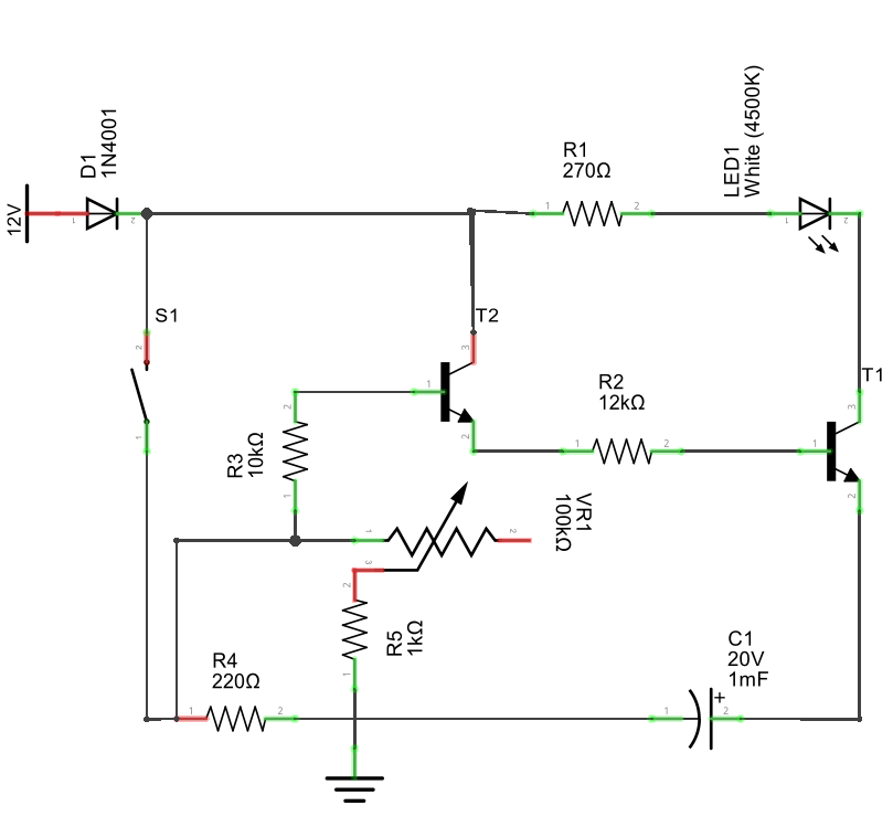
Circuit Design
It’s a transistor based electronic timer. The design of the timer switch is very simple. A push switch triggers the light. The timer is based on the charging and discharging of the capacitor in the RC network. The circuit is very simple and self-explanatory.
How it works
When the switch is closed, the transistor BC547 is turned on. The 1000µF capacitor will charge at the same time through 220Ω resistor.
As BC547 is turned on and its emitter is connected to the base of BC337 through 12K resistor, it will trigger BC337 and it starts conducting.
As the LED is connected to collector of BC337, it is turned on. R1 acts as the current limiting resistor for the LED. When the switch is opened or button is released, BC547 will stay turned on due to the charge from the capacitor. The time of discharge of capacitor through 10KΩ resistor and 100KΩ POT can be set by adjusting the variable resistor.
A 1KΩ resistor acts as a protection resistor when the resistance of variable resistor is completely reduced.
The timer switch in this project will keep the LED turned on for a maximum of approximately 2 minutes.
i have problem with timer the transistors
you mark 1 as the base but leg 2 are the base
you mark 3 as controller but leg 1 are the controller
you mark 2 as the emitter but leg 3 are the emitter
also is R5 connected to the C1 & R4
or is it straight on its own to negative
please help really want to make it work
You are right the numbering in transistor is incorrect. I will update it. Also R5, R4 & C1 are connected to negative.