
In this post we will connect the LCD to GPIO (General Purpose Input Output) pins of PI to display characters on it. We will write a program in PYTHON to send the appropriate commands to the LCD through GPIO and display the needed characters on its screen. This screen will come in handy to display sensor values, interrupt status and also for displaying time. We will be using 4 pin method.
For more details on Pi GPIO pins refer my post here.
Components required
- Raspberry Pi ( any version). I have used Pi 2 B
- 16*2 LCD Module
- 1KΩ resistor ( 2p)
- 10 K Pot
- 1000 μf capacitor
- Miscellaneous ( Breadboard, connecting pins etc.)
Explanation
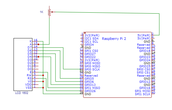
As shown in the Circuit Diagram, we have Interfaced Raspberry Pi with LCD display by connecting 6 GPIO pins of PI to the 16*2 LCD’s Control and Data Transfer Pins. We have used GPIO Pin 26,19,13,06,05 and 11. Pin 26 and 19 are control pins.
16×2 LCD Module has 16 pins, which can be divided into five categories, Power Pins, contrast pin, Control Pins, Data pins and Backlight pins.
|
Category |
Pin NO. |
Pin Name |
Function |
|
Power Pins |
1 |
VSS |
Ground Pin, connected to Ground |
|
|
2 |
VDD or Vcc |
Voltage Pin +5V |
|
Contrast Pin |
3 |
V0 or VEE |
Contrast Setting, connected to Vcc thorough a variable resistor. |
|
Control Pins |
4 |
RS |
Register Select Pin, RS=0 Command mode, RS=1 Data mode |
|
Control Pins |
5 |
RW |
Read/ Write pin, RW=0 Write mode, RW=1 Read mode |
|
Control Pins |
6 |
E |
Enable, a high to low pulse need to enable the LCD |
|
Data Pins |
7-14 |
D0-D7 |
Data Pins, Stores the Data to be displayed on LCD or the command instructions |
|
Backlight Pins |
15 |
LED+ or A |
To power the Backlight +5V |
|
|
16 |
LED- or K |
Backlight Ground |
Usually the LCD requires 8 data lines to provide data to Bits 0-7. However the device can be set to a “4 bit” mode which allows you to send data in two chunks (or nibbles) of 4 bits. This reduces the number of GPIO connections you require when interfacing with your Pi.
Following table will show how I have wired.
|
LCD Pin |
Function |
Pi GPIO Pin |
Pi Pin |
|
01 |
GND |
GND |
Pi -06 |
|
02 |
+5v |
+5v |
Pi-02 |
|
03 |
Contrast |
GND |
Pi -06 |
|
04 |
RS |
GPIO 26 |
Pi-37 |
|
05 |
RW |
GND |
Pi-06 |
|
06 |
E |
GPIO 19 |
Pi-35 |
|
07 |
Data 0 |
|
|
|
08 |
Data 1 |
|
|
|
09 |
Data 2 |
|
|
|
10 |
Data 3 |
|
|
|
11 |
Data 4 |
GPIO 13 |
Pi-33 |
|
12 |
Data 5 |
GPIO 06 |
Pi-31 |
|
13 |
Data 6 |
GPIO 05 |
Pi-29 |
|
14 |
Data 7 |
GPIO 11 |
Pi-23 |
|
15 |
+5v via VR 1K |
+5V |
|
|
16 |
GND |
GND |
Pi-06 |
Since RW pin allows the device to be be put into read or write mode. I wanted to send data to the device but did not want it to send data to the Pi so I tied this pin to ground. Contrast pin has been set to ground but can be connected to VCC through VR.
Once everything is connected as per the circuit diagram, we can turn ON the PI to write the program in PYHTON.
There are many different ways to do it. I will be using
We are going to import GPIO file from library, below function enables us to program GPIO pins of PI. We are also renaming “GPIO” to “IO”, so in the program whenever we want to refer to GPIO pins we will use the word ‘IO’.
import RPi.GPIO as GPIO
GPIO.setwarnings(False)
We can refer the GPIO pins of PI, either by pin number on board or by BCM pin numbers.
GP IO.setmode (IO.BCM)
We are setting 6 GPIO pins as output pins, for Data and Control pins of LCD.
GPIO.setup(LCD_E, GPIO.OUT) # E
GPIO.setup(LCD_RS, GPIO.OUT) # RS
GPIO.setup(LCD_D4, GPIO.OUT) # DB4
GPIO.setup(LCD_D5, GPIO.OUT) # DB5
GPIO.setup(LCD_D6, GPIO.OUT) # DB6
GPIO.setup(LCD_D7, GPIO.OUT) # DB7
After writing the program and executing it, the Raspberry Pi sends characters to LCD one by one and the LCD displays the characters on the screen.
Code
#!/usr/bin/python
#--------------------------------------
#
# lcd_16x2.py
# 16x2 LCD Test
#
# Author : Pintu Shaw
#
# https://digitalab.org
#
#--------------------------------------

# The wiring for the LCD is as follows:
# 1 : GND
# 2 : 5V
# 3 : Contrast (0-5V)*
# 4 : RS (Register Select)
# 5 : R/W (Read Write) - GROUND THIS PIN
# 6 : Enable or Strobe
# 7 : Data Bit 0 - NOT USED
# 8 : Data Bit 1 - NOT USED
# 9 : Data Bit 2 - NOT USED
# 10: Data Bit 3 - NOT USED
# 11: Data Bit 4
# 12: Data Bit 5
# 13: Data Bit 6
# 14: Data Bit 7
# 15: LCD Backlight +5V**
# 16: LCD Backlight GND

#import
import RPi.GPIO as GPIO
import time

# Define GPIO to LCD mapping
LCD_RS = 26
LCD_E = 19
LCD_D4 = 13
LCD_D5 = 06
LCD_D6 = 05
LCD_D7 = 11

# Define some device constants
LCD_WIDTH = 16 # Maximum characters per line
LCD_CHR = True
LCD_CMD = False

LCD_LINE_1 = 0x80 # LCD RAM address for the 1st line
LCD_LINE_2 = 0xC0 # LCD RAM address for the 2nd line

# Timing constants
E_PULSE = 0.0005
E_DELAY = 0.0005

def main():
# Main program block
GPIO.setwarnings(False)
GPIO.setmode(GPIO.BCM) # Use BCM GPIO numbers
GPIO.setup(LCD_E, GPIO.OUT) # E
GPIO.setup(LCD_RS, GPIO.OUT) # RS
GPIO.setup(LCD_D4, GPIO.OUT) # DB4
GPIO.setup(LCD_D5, GPIO.OUT) # DB5
GPIO.setup(LCD_D6, GPIO.OUT) # DB6
GPIO.setup(LCD_D7, GPIO.OUT) # DB7

# Initialise display
lcd_init()

while True:

# Send some test
lcd_string("Rasbperry Pi",LCD_LINE_1)
lcd_string("16x2 LCD Test",LCD_LINE_2)

time.sleep(3) # 3 second delay

# Send some text
lcd_string("1234567890123456",LCD_LINE_1)
lcd_string("abcdefghijklmnop",LCD_LINE_2)

time.sleep(3) # 3 second delay

# Send some text
lcd_string("digitalab.org",LCD_LINE_1)
lcd_string("Projects and more...",LCD_LINE_2)

time.sleep(3)


def lcd_init():
# Initialise display
lcd_byte(0x33,LCD_CMD) # 110011 Initialise
lcd_byte(0x32,LCD_CMD) # 110010 Initialise
lcd_byte(0x06,LCD_CMD) # 000110 Cursor move direction
lcd_byte(0x0C,LCD_CMD) # 001100 Display On,Cursor Off, Blink Off
lcd_byte(0x28,LCD_CMD) # 101000 Data length, number of lines, font size
lcd_byte(0x01,LCD_CMD) # 000001 Clear display
time.sleep(E_DELAY)

def lcd_byte(bits, mode):
# Send byte to data pins
# bits = data
# mode = True for character
# False for command

GPIO.output(LCD_RS, mode) # RS

# High bits
GPIO.output(LCD_D4, False)
GPIO.output(LCD_D5, False)
GPIO.output(LCD_D6, False)
GPIO.output(LCD_D7, False)
if bits&0x10==0x10:
GPIO.output(LCD_D4, True)
if bits&0x20==0x20:
GPIO.output(LCD_D5, True)
if bits&0x40==0x40:
GPIO.output(LCD_D6, True)
if bits&0x80==0x80:
GPIO.output(LCD_D7, True)

# Toggle 'Enable' pin
lcd_toggle_enable()

# Low bits
GPIO.output(LCD_D4, False)
GPIO.output(LCD_D5, False)
GPIO.output(LCD_D6, False)
GPIO.output(LCD_D7, False)
if bits&0x01==0x01:
GPIO.output(LCD_D4, True)
if bits&0x02==0x02:
GPIO.output(LCD_D5, True)
if bits&0x04==0x04:
GPIO.output(LCD_D6, True)
if bits&0x08==0x08:
GPIO.output(LCD_D7, True)

# Toggle 'Enable' pin
lcd_toggle_enable()

def lcd_toggle_enable():
# Toggle enable
time.sleep(E_DELAY)
GPIO.output(LCD_E, True)
time.sleep(E_PULSE)
GPIO.output(LCD_E, False)
time.sleep(E_DELAY)

def lcd_string(message,line):
# Send string to display

message = message.ljust(LCD_WIDTH," ")

lcd_byte(line, LCD_CMD)

for i in range(LCD_WIDTH):
lcd_byte(ord(message[i]),LCD_CHR)

if __name__ == '__main__':

try:
main()
except KeyboardInterrupt:
pass
finally:
lcd_byte(0x01, LCD_CMD)
lcd_string("Goodbye!",LCD_LINE_1)
GPIO.cleanup()
Troubleshooting and things to take care
-
Verify the wiring
-
If display is faint or very dark adjust the contrast by adding a VR of 10K
-
Verify all ground wires
-
If there is any issue in python script, make sure to run using python3.
-
Verify the indention and tab spacing in the file. You may encounter error in compiling if there issue in spacing.
Once you are successful, it can be used to display other values like temperature and other sensor data.
Happy experimenting !!!