

A continuity tester is one of the most useful tools for anyone working with electronics. It helps check whether a wire, switch, connector, or PCB track provides an electrical path between two points.
In this episode of the DigitalLab Beginner Electronics DIY Series, we build a simple DIY continuity tester using a 2N2222 NPN transistor, an LED, and a buzzer.
Instead of stopping at a breadboard demonstration, we develop the circuit into a practical handheld tool powered by a 9V battery. The finished design includes detachable multimeter probes, banana sockets, a power switch, a power indicator LED, and an enclosure.
This project is also a great way for beginners to understand transistor switching, current-limiting resistors, and basic circuit testing.
1. Project overview
The continuity tester provides both visual and audible feedback when the probes detect a low-resistance connection.
The basic operating principle is simple:
- Probes open: The continuity LED remains off and the buzzer is silent.
- Probes connected: The transistor switches on, illuminating the LED and activating the buzzer.
- Increasing resistance: The LED becomes dimmer, while the buzzer response depends on the resistance and circuit conditions.
The circuit uses a 2N2222 transistor as an electronic switch. This keeps the design simple and makes it suitable for a beginner electronics project.
Project features
- Simple transistor-based circuit
- LED indication for continuity
- Audible feedback using a buzzer
- Adjustable circuit sensitivity through resistor selection
- 9V battery operation
- Detachable red and black multimeter probes
- Compact enclosure with a power switch and indicator
2. Components required
The following components are used in the circuit and final assembly.
| Component | Quantity | Purpose |
|---|---|---|
| 2N2222 NPN transistor | 1 | Electronic switching |
| LED for continuity indication | 1 | Visual feedback |
| Green LED for power indication | 1 | Shows when the tester is switched on |
| 1 kΩ resistor | 1 for the continuity LED; another for the power LED | Limits LED current |
| 10 kΩ resistor | 1 | Limits current into the transistor base |
| 2.2 kΩ resistor | 1 | Pulls the transistor base toward ground |
| Buzzer | 1 | Audible feedback |
| 9V battery | 1 | Power supply |
| On/off switch | 1 | Controls the power supply |
| Red and black multimeter probes | 1 pair | Test connections |
| Red and black panel-mount banana sockets | 1 pair | Detachable probe connections |
| Breadboard and jumper wires | As required | Prototype testing |
| Perfboard and solder | As required | Permanent circuit assembly |
| Project enclosure | 1 | Houses the completed tester |
Additional items: battery connector, hookup wire, and mounting hardware as required.
The power indicator LED uses its own current-limiting resistor. The continuity LED and power LED serve different purposes: the green LED indicates that power is on, while the continuity LED responds to the test connection.
3. Circuit diagram
The circuit consists of three main sections:
- The probe and transistor-base input.
- The transistor-controlled LED indicator.
- The buzzer connected to the transistor’s collector switching node.
Refer to the circuit diagram below for the connections used in the working prototype.
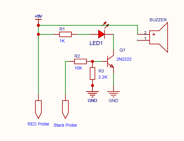
Main circuit connections
- Battery positive connects to the positive supply rail.
- The continuity LED is connected in series with its 1 kΩ current-limiting resistor between the positive supply and the transistor collector.
- The buzzer positive terminal connects to the positive supply.
- The buzzer negative terminal connects to the transistor collector.
- The transistor emitter connects to ground.
- The red probe connects to the positive supply.
- The black probe connects through a 10 kΩ resistor to the transistor base.
- A 2.2 kΩ resistor connects the transistor base to ground.
The transistor’s base-to-ground resistor helps keep the transistor switched off when the probes are open.
Important: The power indicator LED is an additional part of the finished enclosure design. Connect it across the switched 9V supply through its own current-limiting resistor.
4. How the continuity tester works
The heart of the circuit is the 2N2222 NPN transistor.
A transistor can operate as an electronic switch. A small current entering its base allows a larger current to flow between its collector and emitter.
Condition 1: Probes are apart
When the probes are not connected to each other, the input path is open. The base-to-ground resistor keeps the transistor base near ground.
The transistor remains off, so current does not flow through the continuity LED or buzzer.
Result: Continuity LED off and buzzer silent.
Condition 2: Probes touch
When the two probes touch, an electrical path is established between the positive supply and the transistor’s base-input resistor.
Base current flows, switching on the 2N2222 transistor. Current can then flow through the LED branch and buzzer branch.
Result: The continuity LED lights and the buzzer sounds.
Condition 3: Resistance increases
A resistor or imperfect connection between the probes reduces the available base current. As a result, the transistor may not switch on as strongly.
The LED brightness decreases as the test resistance increases. At sufficiently high resistance, the transistor switches off or conducts too little current to produce a visible indication.
The exact response depends on the transistor, resistor values, LED characteristics, buzzer type, and battery voltage.
5. Building the circuit on a breadboard
I first built the LED-only continuity detector on a breadboard. This allowed me to test the transistor switching behavior before adding the buzzer.
Step 1: Build the LED circuit
Connect the 1 kΩ resistor and continuity LED in series between the positive supply and the collector of the 2N2222 transistor.
Connect the transistor emitter to ground.
Step 2: Connect the probe input
Connect the red probe to the positive supply. Connect the black probe through the 10 kΩ resistor to the transistor base.
Add the 2.2 kΩ resistor between the base and ground.
This arrangement helps keep the transistor off when the probes are open.
Step 3: Test the LED-only circuit
Switch on the power and test the circuit with the probes apart and then touching.
Initially, the circuit required some adjustment. After correcting the probe/base connections and experimenting with the base-to-ground resistor, the desired behavior was achieved: the LED remained off with the probes apart and illuminated when the probes touched.
Step 4: Add the buzzer
After confirming the LED-only circuit, I added the buzzer between the positive supply and the transistor collector.
The existing LED circuit was left unchanged.
The combined circuit worked correctly, giving both visual and audible continuity indication.
6. Testing the circuit’s sensitivity
One of the most useful parts of this project was testing how the circuit responded to different resistance values.
I tested several resistors across the probes and adjusted the base-to-ground resistor to find a useful compromise between sensitivity and clear indication.
The following table records the results with the final 2.2 kΩ base-to-ground resistor.
| Test resistance | Observed LED indication |
|---|---|
| 0 Ω – probes touching | Bright |
| Approximately 479 Ω | Bright |
| 1.2 kΩ | Bright |
| 4.7 kΩ | Dim |
| 10 kΩ | Dim |
| 100 kΩ | Off |
| 470 kΩ | Off |
These are observations from my prototype rather than guaranteed thresholds for every build.
The experiment demonstrated how resistor selection affects transistor biasing and the sensitivity of a simple continuity tester.
For checking ordinary wires, switches, connectors, and PCB tracks, the circuit provides a useful basic indication. However, it is not a calibrated resistance meter, and LED brightness alone cannot provide an accurate resistance measurement.
7. Adding the power indicator and switch
A separate power indicator makes the tester easier to use.
Without it, an extinguished continuity LED could mean either that the probes are open or that the tester is switched off.
I added a green power LED to the enclosure. The power LED is connected to the switched positive supply through its own 1 kΩ current-limiting resistor. The continuity LED remains controlled by the transistor.
The result is a simple user interface:
- Green LED on: The tester is powered.
- Continuity LED on: The circuit detects a conducting path.
- Buzzer sounding: Audible indication of continuity.
- Power switch off: The tester is switched off.
Design considerations
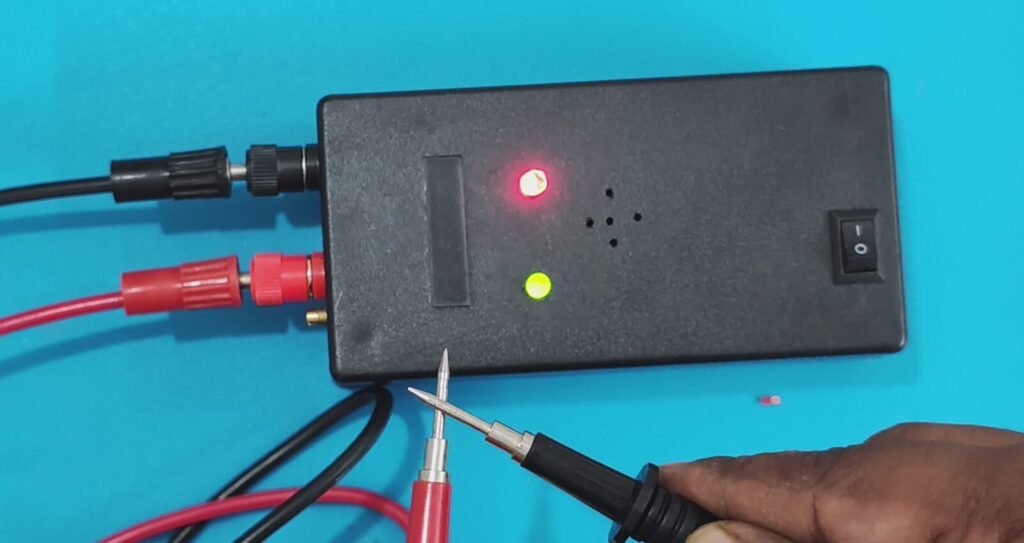
Banana sockets: Red and black panel-mount sockets allow the existing multimeter probe leads to be connected and removed easily. Positioning them on the narrow end keeps the front panel uncluttered.
Power switch: The switch should be accessible when the tester is resting on a workbench or held in the hand.
LED indicators: The green power LED and continuity LED should be clearly visible.
Buzzer opening: Small openings in front of the buzzer allow the sound to escape. The openings should align with the buzzer and should not be obstructed by internal components.
Internal layout: The 9V battery and perfboard need to be secured so that they cannot move around when the tester is carried.
Before drilling an enclosure, measure the mounting diameter of the banana sockets, switch, and LED holders. Also check the internal clearance for the buzzer and battery.
9. Moving from breadboard to perfboard
Once the circuit works reliably, it can be transferred to perfboard for permanent use.
Before soldering, make a placement plan for the transistor, resistors, LED connections, buzzer wiring, and battery leads.
Follow these precautions:
- Disconnect the battery before soldering or modifying the circuit.
- Check the transistor’s base, collector, and emitter connections.
- Verify LED polarity.
- Check buzzer polarity if the buzzer is polarity-sensitive.
- Inspect solder joints for accidental shorts.
- Test the circuit on the bench before closing the enclosure.
- Ensure that the banana sockets and switch cannot contact exposed circuit connections unintentionally.
After assembly, test the open-probe and connected-probe conditions again before using the tester.
10. Safety precautions
A continuity tester should only be used on unpowered circuits.
Never connect this battery-powered tester to a live mains circuit or to a circuit that may contain hazardous voltage. Disconnect the power source and discharge capacitors safely before testing continuity.
The tester provides a basic indication of an electrical path. It does not measure resistance precisely, test every diode or semiconductor correctly, or replace a multimeter for electrical measurements.
Conclusion
This project demonstrates how a small number of inexpensive components can be combined to make a practical electronics tool.
Starting with an LED-only detector, I tested the circuit’s response to different resistance values, adjusted the transistor biasing, and added a buzzer for audible feedback. The final enclosure design incorporates detachable probes, a power switch, and separate power and continuity indicators.
For beginners, this is a useful project for learning transistor switching and circuit troubleshooting while building a tool that can be used in future electronics projects.
In the next beginner electronics projects, we will continue exploring practical circuits and turning simple prototypes into useful tools.
Watch the video: DIY Continuity Tester Using 2N2222 | Beginner Electronics EP3
Subscribe to DigitalLab for more beginner electronics projects, ESP32 tutorials, embedded systems, and practical DIY builds.