
In this post we will see how to interface ESP8266 WiFi module with Raspberry Pi Pico to get internet connectivity.
Raspberry Pi Pico is a low-cost, high-performance board based on the Raspberry Pi RP2040 microcontroller chip. But, it does not support Wi-Fi capabilities hence we have to use an external Wi-Fi module to enable WiFi connectivity for Raspberry Pi Pico.
Note that if you have Raspberry PICO W then it already have Wi-Fi and in that case no need to use any other module.
ESP8266 is a wi-fi module which has self-contained integrated TCP/IP protocol stack that can be easily connected to the microcontroller for gaining access to any Wi-Fi network. For more details on ESP8266 refer my post on ESP8266 wi-fi module.
ESP8266 module
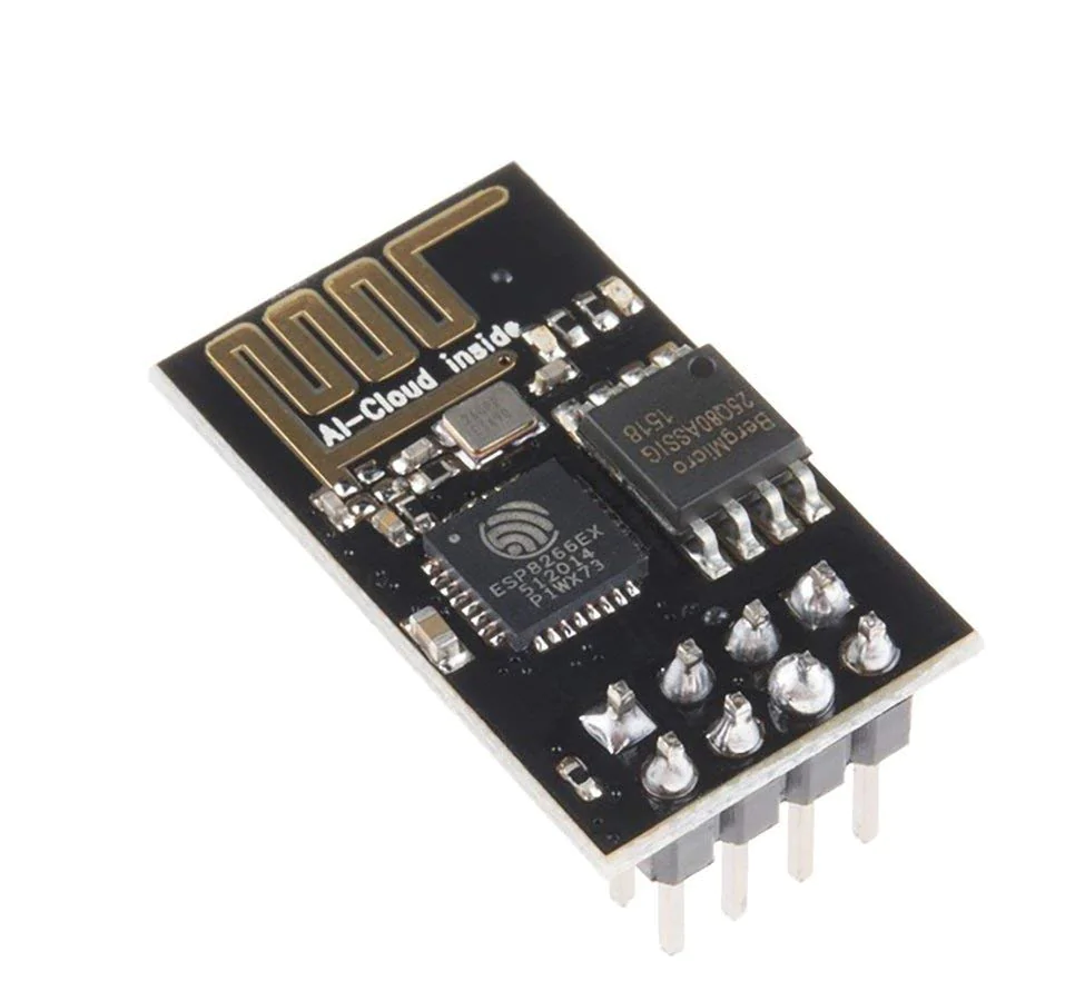
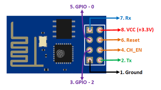
There are many ESP8266 WiFi modules available in the market ranging from ESP-01 to ESP-12. Here we will be using ESP-01. It has 8 pins namely:
- RX
- VCC
- GPIO 0
- RESET
- CH_PD
- GPIO 2
- TX
- and GND
Raspberry Pi PICO
The following table lists the GPIO pins for both UART peripherals which are exposed on Raspberry Pi Pico development board pinouts.
| UART Pins | GPIO Pins |
|---|---|
| UART0-TX | GP0/GP12/GP16 |
| UART0-RX | GP1/GP13/GP17 |
| UART1-TX | GP4/GP8 |
| UART1-RX | GP5/GP9 |
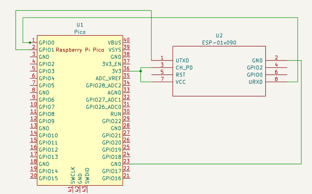
Connection Diagram
We will use pin VCC, EN, GND, RX and TX and connect RX and TX pins of the module with the UART pins of the Pi Pico board. Refer the connection diagram below:
Code
The following Micro Python script of Raspberry Pi Pico sends AT commands to the ESP8266 module to configure ESP8266 as a TCP web server. For more details on AT Command refer the ES8266 AT Instruction set.
import uos
import machine
import utime

recv_buf="" # receive buffer global variable

print()
print("Machine: \t" + uos.uname()[4])
print("MicroPython: \t" + uos.uname()[3])

uart0 = machine.UART(0, baudrate=115200)
print(uart0)

def Rx_ESP_Data():
    recv=bytes()
    while uart0.any()>0:
        recv+=uart0.read(1)
    res=recv.decode('utf-8')
    return res

def Connect_WiFi(cmd, uart=uart0, timeout=3000):
    print("CMD: " + cmd)
    uart.write(cmd)
    utime.sleep(7.0)
    Wait_ESP_Rsp(uart, timeout)
    print()

def Send_AT_Cmd(cmd, uart=uart0, timeout=3000):
    print("CMD: " + cmd)
    uart.write(cmd)
    Wait_ESP_Rsp(uart, timeout)
    print()

def Wait_ESP_Rsp(uart=uart0, timeout=3000):
    prvMills = utime.ticks_ms()
    resp = b""
    while (utime.ticks_ms()-prvMills)<timeout:
        if uart.any():
            resp = b"".join([resp, uart.read(1)])
    print("resp:")
    try:
        print(resp.decode())
    except UnicodeError:
        print(resp)

Send_AT_Cmd('AT\r\n')          #Test AT startup
Send_AT_Cmd('AT+GMR\r\n')      #Check version information
Send_AT_Cmd('AT+CIPSERVER=0\r\n')      #Check version information
Send_AT_Cmd('AT+RST\r\n')      #Check version information
Send_AT_Cmd('AT+RESTORE\r\n')  #Restore Factory Default Settings
Send_AT_Cmd('AT+CWMODE?\r\n')  #Query the WiFi mode
Send_AT_Cmd('AT+CWMODE=1\r\n') #Set the WiFi mode = Station mode
Send_AT_Cmd('AT+CWMODE?\r\n')  #Query the WiFi mode again
#Send_AT_Cmd('AT+CWLAP\r\n', timeout=10000) #List available APs
Connect_WiFi('AT+CWJAP="SSIDNAME","Password"\r\n', timeout=5000) #Connect to AP
Send_AT_Cmd('AT+CIFSR\r\n')    #Obtain the Local IP Address
utime.sleep(3.0)
Send_AT_Cmd('AT+CIPMUX=1\r\n')    #Obtain the Local IP Address
utime.sleep(1.0)
Send_AT_Cmd('AT+CIPSERVER=1,80\r\n')    #Obtain the Local IP Address
utime.sleep(1.0)
print ('Starting connection to ESP8266...')
while True:
    res =""
    res=Rx_ESP_Data()
    utime.sleep(2.0)
    if '+IPD' in res: # if the buffer contains IPD(a connection), then respond with HTML handshake
        id_index = res.find('+IPD')
        print("resp:")
        print(res)
        connection_id =  res[id_index+5]
        print("connectionId:" + connection_id)
        print ('! Incoming connection - sending webpage')
        uart0.write('AT+CIPSEND='+connection_id+',200'+'\r\n')
        utime.sleep(1.0)
        uart0.write('HTTP/1.1 200 OK'+'\r\n')
        uart0.write('Content-Type: text/html'+'\r\n')
        uart0.write('Connection: close'+'\r\n')
        uart0.write(''+'\r\n')
        uart0.write('<!DOCTYPE HTML>'+'\r\n')
        uart0.write('<html>'+'\r\n')
        uart0.write('<body><center><h1>Raspberry Pi Pico Web Server</h1></center>'+'\r\n')
        uart0.write('<center><h2>*-----Digitalab.org-----*</h2></center>'+'\r\n')
        uart0.write('</body></html>'+'\r\n')
        utime.sleep(4.0)
        Send_AT_Cmd('AT+CIPCLOSE='+ connection_id+'\r\n') # once file sent, close connection
        utime.sleep(2.0)
        recv_buf="" #reset buffer
        print ('Waiting For connection...')
How to connect and run ESP8266 WiFi Module with Raspberry Pi Pico
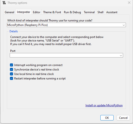
Connect Raspberry Pi Pico to laptop USB and open Thorny. Select MicroPython (Raspberry Pi Pico) and PORT from the options screen as shown below.
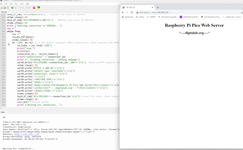
Next, run the program. You should see the output in the shell window. Get the IP address and open it in browser. Refer the screenshot below.
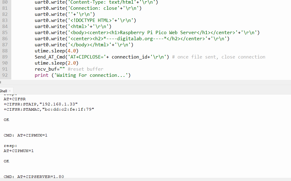
Browser should show the html content as shown below.
We are done now configuring and setting up ESP8266 WiFi Module with Raspberry Pi Pico. We have assumed that ESP8266 firmware is ok. If not you need to flash with the correct firmware.
ESP8266 Firmware Flashing
- USB<>Serial 3.3V converter
- Connect ESP-01 or ESP-01S Module to Laptop in Programming Mode (Short G0 Pin and GND Pin) and Pull CH_PD up ( connect to 3.3v).
- Use ESP8266 Flasher to flash latest firmware in ESP-01/ESP-01S Module.
- RESET ESP-01 Module before testing AT Commands (Short RST with GND Pin).
Note that ESP8266 should be connected to 3.3v only. Also, after downloading the firmware, reset it by connecting GND pin to RST pin.