

In this project, we build an electronic dice circuit using two popular integrated circuits: the NE555 timer and the CD4017 decade counter. This project is part of the DigitalLab Beginner Electronics Series and is designed to help beginners understand timer circuits, digital counters, and sequential LED operation through a practical breadboard experiment.
The NE555 generates clock pulses, while the CD4017 responds to these pulses by activating its outputs one after another. LEDs connected to the counter outputs visually demonstrate how a digital counting circuit works.
Project Overview
Project name: Electronic Dice Using NE555 and CD4017
Difficulty: Beginner
Power supply: 9V DC
Main ICs: NE555 timer and CD4017BE decade counter
Build method: Breadboard prototype
Components Required
| Component | Quantity |
|---|---|
| NE555 timer IC | 1 |
| CD4017BE decade counter IC | 1 |
| LEDs | 6 |
| 1 K Current-limiting resistors for LEDs | 6 |
| 10 kΩ resistor | 1 |
| 47 kΩ resistor | 1 |
| 1 µF capacitor | 1 |
| 100 nF capacitor | 1 |
| Push button | 1 |
| Breadboard | 1 |
| Jumper wires | As required |
| 9V DC power supply | 1 |
The LED resistors should be selected according to the supply voltage and LED characteristics.
Note: Do not connect LEDs directly to the IC outputs without current-limiting resistors.
How the Circuit Works
The circuit has two main stages.
1. NE555 Timer Circuit ( Stage 1)
The NE555 is configured as an astable oscillator. In this mode, it continuously generates HIGH and LOW pulses without requiring a separate trigger for every cycle.
The timing resistors and capacitor determine the approximate pulse frequency. In this project, the timing network uses a 10 kΩ resistor, a 47 kΩ resistor, and a 1 µF capacitor.
The output at pin 3 of the NE555 is connected to the clock input of the CD4017.
2. CD4017 Decade Counter (Stage 2)
The CD4017 is a decade counter with ten decoded outputs. Each incoming clock pulse advances the active output to the next state.
The six LEDs are connected to the first six counter outputs:
| LED | CD4017 output | IC pin |
|---|---|---|
| LED 1 | Q0 | 3 |
| LED 2 | Q1 | 2 |
| LED 3 | Q2 | 4 |
| LED 4 | Q3 | 7 |
| LED 5 | Q4 | 10 |
| LED 6 | Q5 | 1 |
As the counter advances, the LEDs illuminate in sequence. The speed of the sequence depends on the NE555 timing components.
Circuit Connections
NE555 Connections for Stage 1
| NE555 pin | Connection |
|---|---|
| Pin 1 | GND |
| Pin 2 | Connected to pin 6 |
| Pin 3 | Output to CD4017 pin 14. Note: In Stage 1 It is connected to LED. Refer circuit in fig1. |
| Pin 4 | Reset push-button circuit |
| Pin 5 | Optional 10 nF capacitor to GND |
| Pin 6 | Connected to pin 2 |
| Pin 7 | Timing resistor junction |
| Pin 8 | +9V |
Connect a 10 kΩ resistor between +9V and pin 7. Connect a 47 kΩ resistor between pin 7 and the joined pins 2 and 6. Connect the positive terminal of the 1 µF timing capacitor to pins 2 and 6, and its negative terminal to GND. A 100 nF capacitor across the supply rails near the ICs helps reduce supply noise.
Refer the below circuit diagram for reference.
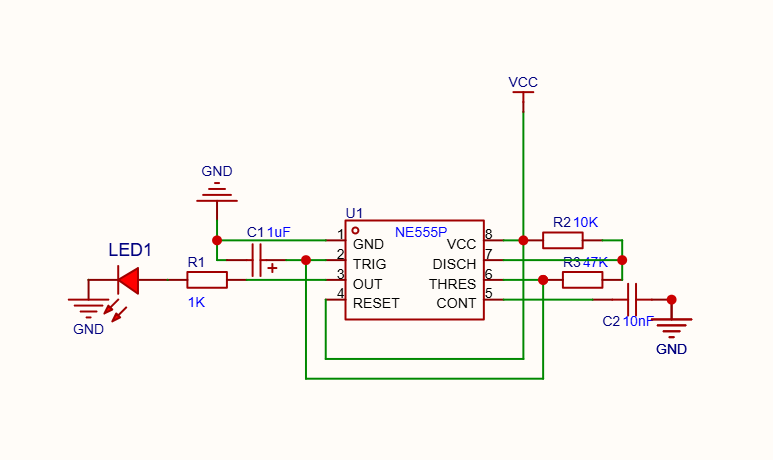
Note: In Stage 1 Output from pin 3 is connected to LED to test in isolation.
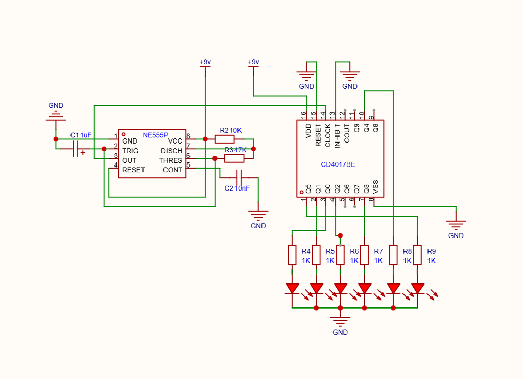
CD4017 Connections ( Stage 2 without switch and reset)
| CD4017 pin | Connection |
|---|---|
| Pin 16 | +9V |
| Pin 8 | GND |
| Pin 14 | Clock input from NE555 pin 3 |
| Pin 13 | GND (clock inhibit disabled) |
| Pin 15 | GND for normal counting |
| Pins 3, 2, 4, 7, 10, 1 | LED 1 through LED 6, respectively |
Connect the anode of each LED to its counter output through a suitable current-limiting resistor, with the cathode connected to GND.
Ensure both ICs share the same +9V supply and common GND.
Final Stage – Push-Button Control
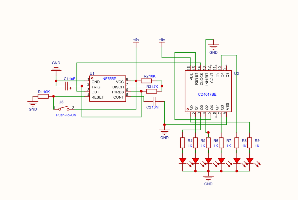
The push button controls the NE555 RESET input at pin 4.
A 10 kΩ resistor pulls pin 4 to GND. A normally open push button connects pin 4 to +9V when pressed.
When the button is pressed, the NE555 is enabled and generates clock pulses. When the button is released, pin 4 is pulled LOW, stopping the clock. This provides a simple way to demonstrate timer control
Testing the Circuit
Build the circuit in stages to make troubleshooting easier.
- Assemble the NE555 oscillator and verify that its output produces pulses. ( Stage 1)
- Connect the NE555 output to CD4017 pin 14. ( Stage 2)
- Connect CD4017 pin 13 to GND.
- Connect pin 15 to GND for normal counting.
- Connect the six LEDs to outputs Q0 through Q5.
- Power the circuit using a suitable 9V supply and observe the LED sequence.
- Test the push button to verify that it starts and stops the clock. ( Stage 3 – Final)
Always disconnect the power before moving wires or changing IC connections.
Troubleshooting Notes
LEDs do not change: Check the NE555 output connection to CD4017 pin 14, common GND, and the power connections to both ICs.
No LEDs illuminate: Verify LED polarity, series resistors, IC orientation, and the supply connections.
Counter behaves unpredictably: Make sure CD4017 pin 13 is connected to GND. Leaving the clock-inhibit input floating can cause unreliable operation.
Automatic reset does not work correctly: The intended six-state sequence uses CD4017 pin 5 (Q6) connected to pin 15 (RESET). In testing, this connection caused inconsistent LED sequencing. For the demonstrated version, keep pin 15 connected to GND and leave pin 5 disconnected from RESET. The counter will continue through its ten states, while only six outputs have LEDs connected.
Video Demonstration
Watch the Electronic Dice project video to see the breadboard circuit, component connections, and sequential LED operation.
YouTube video: https://www.youtube.com/watch?v=QVT66wZDCMk
Conclusion
This project is a useful introduction to digital electronics. By combining the NE555 timer with the CD4017 counter, beginners can explore clock generation, sequential outputs, reset logic, and practical breadboard wiring.
Although the automatic six-state reset needs further refinement, the circuit successfully demonstrates how a timer and decade counter can control a series of LEDs. It also provides a foundation for future projects involving digital counters, LED patterns, and electronic games.
Follow DigitalLab for more beginner electronics projects, practical DIY circuits, ESP32 tutorials, and hands-on experiments.