

Welcome to Episode 1 of the DigitalLab ESP32 Beginner Series!
In this tutorial, we will learn how to use GPIO (General Purpose Input/Output) pins on an ESP32 development board. We will start with simple circuits and gradually explore how the ESP32 can interact with different electronic components.
We will work with four basic components:
- LED – to understand digital output
- Push button – to understand digital input
- Active buzzer – to generate an ON/OFF sound
- Passive buzzer – to generate different sound frequencies
By the end of this tutorial, you will understand the basics of ESP32 GPIO and how to control external components using Arduino IDE.
1. What is GPIO?
GPIO stands for General Purpose Input/Output.
GPIO pins are programmable pins on a microcontroller that allow it to communicate with external electronic components.
A GPIO pin can generally be configured in two ways:
- Input: The ESP32 reads a signal from an external component, such as a push button.
- Output: The ESP32 sends a signal to control a component, such as an LED or buzzer.
For this tutorial, we are using an ESP32 DevKit V1 development board with 38 pins.
2. Components required
You will need the following components:
| Component | Quantity |
|---|---|
| ESP32 DevKit V1 (38-pin) | 1 |
| LED | 1 |
| 220Ω or 330Ω resistor | 1 |
| Push button | 1 |
| Active buzzer | 1 |
| Passive buzzer | 1 |
| 2N2222 transistor | 1 |
| 1kΩ resistor | 1 |
| Breadboard | 1 |
| Jumper wires | As required |
| USB cable | 1 |
3. ESP32 power supply and GPIO voltage
The ESP32 development board can be powered through its USB port. The board’s onboard voltage regulator provides the required 3.3V supply to the ESP32 chip.
An important point to remember is that ESP32 GPIO pins operate at 3.3V logic levels.
- GPIO HIGH = approximately 3.3V
- GPIO LOW = approximately 0V
- Never apply 5V directly to an ESP32 GPIO pin.
- Do not connect a 5V signal to the ESP32’s 3.3V pin.
For this project, we will power the ESP32 through USB.
4. GPIO pin allocation
We will use the following GPIO pins throughout this tutorial.
| Component | ESP32 GPIO |
|---|---|
| LED | GPIO18 |
| Push button | GPIO21 |
| Buzzer | GPIO23 |
We will reuse GPIO23 for the active and passive buzzer demonstrations, testing them separately.
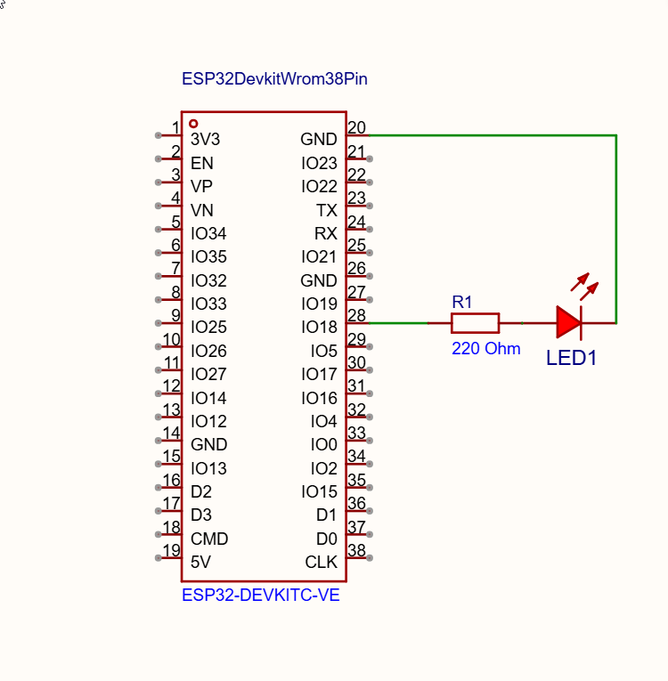
5. Stage 1 – Controlling an LED using GPIO
Let’s start with a simple LED circuit to understand how an ESP32 GPIO pin works as a digital output.
Circuit connections
Connect the LED as follows:
- Connect GPIO18 to a 220Ω resistor.
- Connect the other end of the resistor to the LED’s anode (longer leg).
- Connect the LED’s cathode (shorter leg) to GND.
The resistor limits the current flowing through the LED and protects both the LED and the GPIO pin.
Arduino IDE code
#define LED_PIN 18

void setup() {
  pinMode(LED_PIN, OUTPUT);
}

void loop() {
  digitalWrite(LED_PIN, HIGH);
  delay(1000);

  digitalWrite(LED_PIN, LOW);
  delay(1000);
}
Understanding the code
pinMode()configures GPIO18 as an output.digitalWrite(LED_PIN, HIGH)turns the LED ON.digitalWrite(LED_PIN, LOW)turns the LED OFF.delay(1000)pauses the program for one second.
Upload the code to the ESP32. The LED should turn ON for one second and OFF for one second continuously.
This is our first example of using an ESP32 GPIO pin as a digital output.
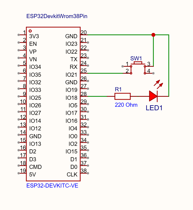
6. Stage 2 – Reading a push button using GPIO
Now let’s use a push button to understand digital input.
Instead of sending a signal to a component, the ESP32 will read the state of the button and control the LED accordingly.
Circuit connections
Keep the LED circuit connected and add a push button:
- Connect one side of the push button to GPIO21.
- Connect the opposite side to GND.
If you are using a four-legged tactile push button, place it across the breadboard’s centre gap.
We will use the ESP32’s internal pull-up resistor, so an external pull-up resistor is not required.
Understanding INPUT_PULLUP
When using INPUT_PULLUP, the ESP32 internally connects the input pin to a pull-up resistor.
This means:
- Button released = HIGH
- Button pressed = LOW
This is called active-low input logic.
Arduino IDE code
#define LED_PIN 18
#define BUTTON_PIN 21

void setup() {
  pinMode(LED_PIN, OUTPUT);
  pinMode(BUTTON_PIN, INPUT_PULLUP);

  Serial.begin(115200);
}

void loop() {
  int buttonState = digitalRead(BUTTON_PIN);

  if (buttonState == LOW) {
    digitalWrite(LED_PIN, HIGH);
    Serial.println("Button Pressed - LED ON");
  } else {
    digitalWrite(LED_PIN, LOW);
    Serial.println("Button Released - LED OFF");
  }

  delay(100);
}
Understanding the code
pinMode(BUTTON_PIN, INPUT_PULLUP)configures GPIO21 as an input with an internal pull-up resistor.digitalRead()reads the button state.- When the button is pressed, the input becomes LOW and the LED turns ON.
- When the button is released, the input becomes HIGH and the LED turns OFF.
Open the Serial Monitor in Arduino IDE and set the baud rate to 115200 to see the button status.
You have now learned how to use an ESP32 GPIO pin as a digital input.
7. Stage 3A – Controlling an active buzzer
An active buzzer contains an internal oscillator. When the correct DC voltage is applied, it generates a sound.
This makes it easy to control using a simple ON/OFF signal.
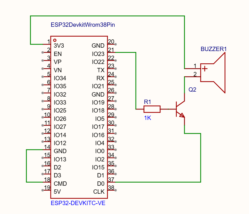
For this demonstration, we use a 2N2222 transistor as a switching device.
Why use a transistor?
A transistor allows a GPIO pin to control a buzzer without requiring the buzzer’s current to flow directly through the ESP32 GPIO.
It also allows the buzzer to use a separate supply, provided the buzzer is rated for that voltage.
Circuit connections
Connect the active buzzer using the following arrangement:
- Connect GPIO23 to a 1kΩ resistor.
- Connect the other end of the resistor to the 2N2222 transistor’s base.
- Connect the transistor’s emitter to GND.
- Connect the transistor’s collector to the negative terminal of the active buzzer.
- Connect the buzzer’s positive terminal to its rated positive supply.
- Connect the supply negative terminal to ESP32 GND.
A 10kΩ resistor between the transistor’s base and emitter can be used as a pull-down resistor to keep the transistor OFF when the GPIO is not actively driving it.
Important: Check the pinout of your particular 2N2222 transistor before connecting it. Pin arrangements can differ between manufacturers and package variants.
Arduino IDE code
#define BUZZER_PIN 23

void setup() {
  pinMode(BUZZER_PIN, OUTPUT);
}

void loop() {
  digitalWrite(BUZZER_PIN, HIGH);
  delay(1000);

  digitalWrite(BUZZER_PIN, LOW);
  delay(1000);
}
When GPIO23 goes HIGH, the transistor switches ON and the active buzzer produces sound. When GPIO23 goes LOW, the transistor switches OFF and the buzzer stops.
8. Stage 3B – Generating different tones using a passive buzzer
Unlike an active buzzer, a passive buzzer does not have an internal oscillator.
It needs an alternating electrical signal to generate sound. By changing the frequency of this signal, we can produce different tones.
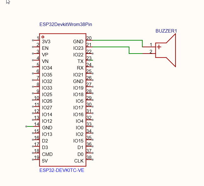
For a simple two-terminal passive piezo buzzer, we can generate the signal directly from an ESP32 GPIO pin.
Circuit connections
- Connect GPIO23 to one terminal of the passive buzzer.
- Connect the other buzzer terminal to GND.
This simple arrangement is suitable for a low-current passive piezo element. Make sure you identify the component correctly and stay within its electrical ratings.
Arduino IDE code
/*
  DigitalLab ESP32 Beginner Series
  EP1 - Stage 3B: Passive Buzzer

  Board: ESP32 DevKit V1
  Buzzer: Passive
  GPIO: 23
*/

#define BUZZER_PIN 23

void setup() {
  Serial.begin(115200);
}

void loop() {

  // Low frequency
  Serial.println("500 Hz");
  tone(BUZZER_PIN, 500);
  delay(2000);

  // Medium frequency
  Serial.println("1000 Hz");
  tone(BUZZER_PIN, 1000);
  delay(2000);

  // High frequency
  Serial.println("1500 Hz");
  tone(BUZZER_PIN, 1500);
  delay(2000);

  // Stop buzzer
  noTone(BUZZER_PIN);
  Serial.println("Silence");
  delay(2000);
}
Understanding the code
tone()generates a square-wave signal at the specified frequency.delay(2000)allows the buzzer to play the tone for 2 seconds.noTone()stops the signal.
You can experiment with different frequency values to hear how the sound changes.
The loudness of a passive buzzer depends on its construction, resonant frequency, drive voltage and circuit arrangement. Changing frequency mainly changes the pitch, not necessarily the volume.
9. Active buzzer vs passive buzzer
Both buzzers produce sound, but they work differently.
| Feature | Active buzzer | Passive buzzer |
|---|---|---|
| Internal oscillator | Yes | No |
| DC voltage produces sound | Yes, at its rated voltage | No continuous tone |
| Frequency control | Usually fixed | Programmable |
| Control method | ON/OFF | Generate a frequency |
| Typical application | Simple alarms | Different tones and melodies |
An active buzzer is useful when you need a simple alarm or notification sound. A passive buzzer is more suitable when you want to generate different tones or simple melodies.
10. What did we learn?
In this episode, we covered the fundamentals of ESP32 GPIO through practical circuits.
We learned how to:
- Configure an ESP32 GPIO pin as a digital output.
- Turn an LED ON and OFF using
digitalWrite(). - Read a push button using
digitalRead(). - Use the internal pull-up resistor with
INPUT_PULLUP. - Control an active buzzer using a transistor.
- Generate different sound frequencies using a passive buzzer.
- Work safely with the ESP32’s 3.3V GPIO logic.
These concepts form the foundation for more advanced ESP32 projects.
11. What’s next?
In the next episode of the DigitalLab ESP32 Beginner Series, we will explore analog inputs and ADC (Analog-to-Digital Conversion).
We will use components such as a potentiometer and an LDR to understand how the ESP32 reads changing voltage levels and converts them into digital values.
Watch the video
Watch the complete practical demonstration here:
ESP32 GPIO Tutorial for Beginners | LED, Push Button, Active & Passive Buzzer (EP1)
If you found this tutorial useful, please like the video, subscribe to the DigitalLab YouTube channel and follow the blog for more electronics projects and ESP32 tutorials.
DigitalLab – Learn, Build and Experiment!