

Welcome to Episode 2 of the DigitalLab ESP32 Beginner Series!
In this episode, we will explore how to read analog signals using the ESP32’s built-in Analog-to-Digital Converter (ADC).
Unlike digital inputs, which have only two states (HIGH and LOW), analog inputs can represent a range of voltage levels. The ESP32 can measure these varying voltages and convert them into digital values that can be processed by a program.
To understand this practically, we will build two simple projects:
- Potentiometer-based LED Brightness Control
- LDR-based Automatic Light Sensor
These projects will help beginners understand ADC, analog voltage, voltage dividers, PWM and sensor-based automation.
What is Analog Input?
An analog signal is a continuously varying electrical signal that can have different voltage levels within a specified range.
For example, a potentiometer can provide a variable voltage between 0V and 3.3V depending on its knob position.
The ESP32 cannot directly process analog voltage as a digital value. It uses an Analog-to-Digital Converter (ADC) to convert the input voltage into a numerical value.
Understanding ADC in ESP32
The ESP32 DevKit V1 supports 12-bit ADC resolution in our experiments.
A 12-bit ADC provides 4096 possible digital values, ranging from:
- 0 – Minimum reading
- 2048 – Approximately halfway
- 4095 – Maximum reading
For our experiments, we will use GPIO34 as the analog input pin.
The Arduino IDE provides the analogRead() function to read analog values from an ESP32 ADC pin.
Stage 1 – Potentiometer and ADC: Controlling LED Brightness
In the first experiment, we will use a 10K potentiometer to generate a variable analog voltage.
The ESP32 reads this voltage through GPIO34 and uses the reading to control the brightness of an LED connected to GPIO25.
Components Required
- ESP32 DevKit V1 (38-pin)
- 10K potentiometer
- LED
- 220Ω resistor
- Breadboard
- Jumper wires
Circuit Connections
Potentiometer connections:
| Potentiometer Pin | ESP32 Connection |
|---|---|
| Outer pin 1 | 3.3V |
| Middle pin (wiper) | GPIO34 |
| Outer pin 2 | GND |
The two outer terminals can be interchanged. This only reverses the direction in which the ADC readings increase.
LED connections:
| LED Connection | ESP32 Connection |
|---|---|
| Anode (+) | GPIO25 through 220Ω resistor |
| Cathode (-) | GND |
The 220Ω resistor limits current through the LED.
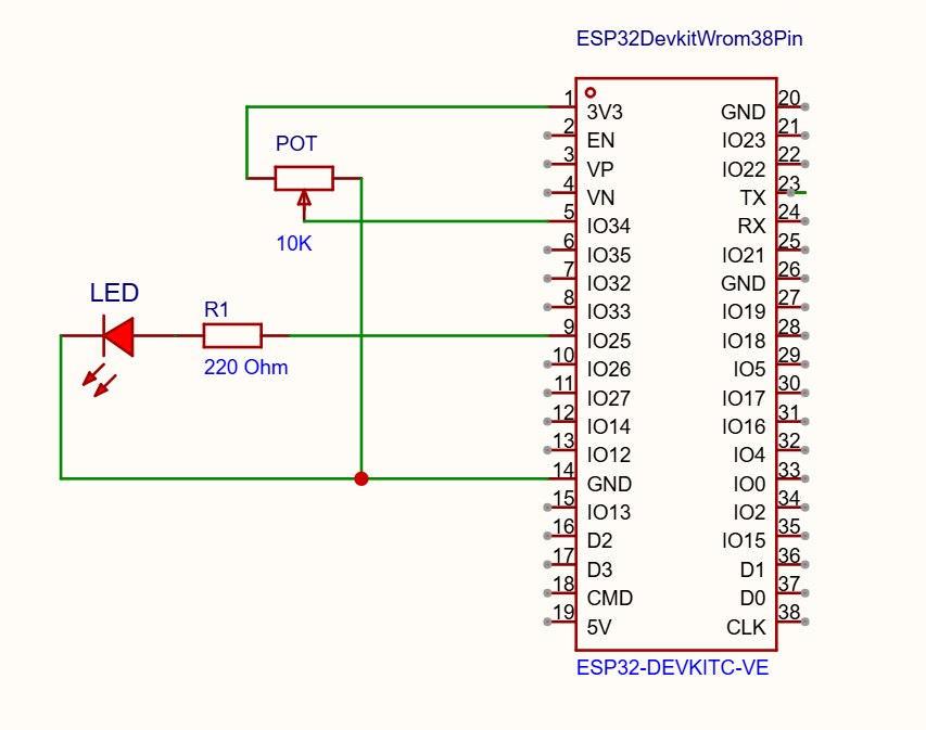
Arduino IDE Code – Potentiometer and ADC
// DigitalLab - ESP32 Beginner Series
// EP2: Analog Input and ADC
// Stage 1: Potentiometer-controlled LED brightness

const int POT_PIN = 34;
const int LED_PIN = 25;

void setup() {
  Serial.begin(115200);

  analogReadResolution(12);
  analogWriteResolution(LED_PIN, 8);

  pinMode(LED_PIN, OUTPUT);

  Serial.println("DigitalLab - ESP32 ADC Experiment");
}

void loop() {
  int adcValue = analogRead(POT_PIN);

  // Calculate approximate voltage
  float voltage = (adcValue / 4095.0) * 3.3;

  // Convert ADC value into LED brightness
  int brightness = map(adcValue, 0, 4095, 0, 255);
  brightness = constrain(brightness, 0, 255);

  // Control LED brightness
  analogWrite(LED_PIN, brightness);

  // Display readings
  Serial.print("ADC Value: ");
  Serial.print(adcValue);

  Serial.print(" | Voltage (approx): ");
  Serial.print(voltage, 2);
  Serial.print(" V");

  Serial.print(" | LED Brightness: ");
  Serial.println(brightness);

  delay(200);
}
Understanding the Code
1. Reading Analog Values
int adcValue = analogRead(POT_PIN);
This reads the voltage supplied by the potentiometer through GPIO34.
2. Calculating Approximate Voltage
float voltage = (adcValue / 4095.0) * 3.3;
This calculates an approximate voltage based on the ADC reading and the assumed 3.3V reference range.
3. Converting ADC Values into PWM
int brightness = map(adcValue, 0, 4095, 0, 255);
The ADC reading ranges from 0 to 4095, while our LED brightness control uses an 8-bit range of 0 to 255.
The map() function converts one range into another.
4. Controlling LED Brightness
analogWrite(LED_PIN, brightness);
This generates a PWM signal to control the LED brightness.
Expected Output
As you rotate the potentiometer, the ADC readings and LED brightness change.
| Potentiometer Position | Approx. ADC Value | LED Brightness |
|---|---|---|
| Minimum | 0 | 0 |
| 25% | 1024 | 64 |
| 50% | 2048 | 128 |
| 75% | 3072 | 191 |
| Maximum | 4095 | 255 |
These are illustrative values. Actual ESP32 ADC readings may vary.
What we learned in Stage 1:
- Reading analog voltage using ESP32.
- Understanding 12-bit ADC resolution.
- Displaying ADC readings in Serial Monitor.
- Converting ADC readings into approximate voltage.
- Using PWM to control LED brightness.
<image>
Stage 2 – LDR Light Sensor: Automatic LED Control
In the second experiment, we will use an LDR (Light Dependent Resistor) to detect surrounding light intensity.
An LDR changes its resistance depending on the amount of light falling on its surface.
- More light: LDR resistance decreases.
- Less light: LDR resistance increases.
By combining the LDR with a 10K resistor, we can create a voltage divider and read the changing voltage using the ESP32 ADC.
Components Required
- ESP32 DevKit V1 (38-pin)
- Small LDR (Light Dependent Resistor)
- 10K resistor
- LED
- 220Ω resistor
- Breadboard
- Jumper wires
Circuit Connections
We will connect the LDR and 10K resistor as a voltage divider.
Circuit connections:
| Component | Connection |
|---|---|
| LDR leg 1 | ESP32 3.3V |
| LDR leg 2 | GPIO34 |
| 10K resistor leg 1 | GPIO34 |
| 10K resistor leg 2 | GND |
The junction between the LDR and 10K resistor connects to GPIO34.
The LED uses the same GPIO25 connection as Stage 1, with a 220Ω series resistor.
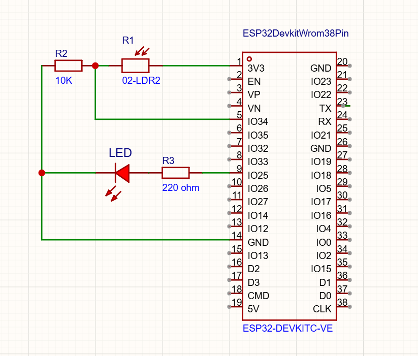
How the LDR Circuit Works
When more light falls on the LDR, its resistance decreases. This increases the voltage at the junction connected to GPIO34.
When the LDR is covered, its resistance increases and the junction voltage decreases.
The ESP32 reads these voltage changes as ADC values.
With this circuit arrangement:
- Bright environment → Higher ADC reading.
- Dark environment → Lower ADC reading.
Arduino IDE Code – LDR Light Sensor
/*
  DigitalLab - ESP32 Beginner Series
  EP2: Analog Input and ADC
  Stage 2: LDR Light Sensor
*/

const int LDR_PIN = 34;
const int LED_PIN = 25;

// Initial threshold - adjust after testing
const int LIGHT_THRESHOLD = 1800;

void setup() {
  Serial.begin(115200);

  analogReadResolution(12);

  pinMode(LED_PIN, OUTPUT);

  Serial.println("DigitalLab - LDR Light Sensor");
}

void loop() {

  int ldrValue = analogRead(LDR_PIN);

  Serial.print("LDR ADC Value: ");
  Serial.print(ldrValue);

  if (ldrValue < LIGHT_THRESHOLD) {

    digitalWrite(LED_PIN, HIGH);
    Serial.println(" | Dark - LED ON");

  } else {

    digitalWrite(LED_PIN, LOW);
    Serial.println(" | Bright - LED OFF");

  }

  delay(300);
}
Understanding the Code
1. Reading LDR Values
int ldrValue = analogRead(LDR_PIN);
This reads the analog voltage generated by the LDR voltage divider.
2. Setting a Threshold
const int LIGHT_THRESHOLD = 1800;
This defines the ADC value used to distinguish between bright and dark conditions.
The value 1800 is an initial example. The appropriate threshold depends on the LDR, resistor and surrounding lighting conditions.
3. Automatic LED Control
if (ldrValue < LIGHT_THRESHOLD) {
    digitalWrite(LED_PIN, HIGH);
} else {
    digitalWrite(LED_PIN, LOW);
}
When the ADC reading falls below the threshold, the LED turns ON.
Testing the LDR Sensor
After uploading the code:
- Open Serial Monitor at 115200 baud.
- Observe the ADC reading under normal room lighting.
- Cover the LDR using your finger.
- Shine a mobile flashlight on the LDR.
- Observe the changes in ADC readings.
- Adjust the threshold value and demonstrate how it affects LED switching.
What we learned in Stage 2:
- Understanding how an LDR works.
- Building a voltage divider circuit.
- Reading light intensity using ESP32 ADC.
- Using conditional statements to control an LED.
- Adjusting threshold values for automatic light detection.
Important ESP32 Wiring Precautions
Keep these points in mind while building both projects:
- Use 3.3V for the potentiometer and LDR voltage divider.
- ESP32 GPIO pins are not 5V tolerant.
- Never apply 5V to GPIO34.
- Use a 220Ω resistor in series with the LED.
- Ensure all circuit grounds are connected to ESP32 GND.
- GPIO34 is an input-only pin, making it suitable for analog sensor readings.
Watch the EP2 Video:
Conclusion
In this episode of the DigitalLab ESP32 Beginner Series, we explored analog input and ADC using two practical projects.
In Stage 1, we used a potentiometer to generate variable analog voltage and controlled LED brightness using PWM. In Stage 2, we used an LDR to detect surrounding light intensity and automatically switched an LED based on a configurable threshold. These experiments provide a practical introduction to reading analog signals and using sensors with ESP32.
In the next episode, we will explore temperature and humidity measurement using an ESP32 and a digital temperature and humidity sensor.