
In this post I am going to show how to connect 16*2 LCD using I2C with Arduino. In my earlier article “How to connect 16*2 LCD display Arduino UNO “How to connect 16*2 LCD display Arduino UNO“. I had used more than 12 wires to connect to display. But with I2C serial adapter we are going to use only 4 wires.
What you need?
- I2C Serial interface
- 16*2 LCD
- Arduino UNO
- Some wires and
- Lots of patience
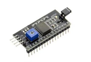
It has total of 20 pins out of which 16 pins are connected to LCD and 4 pins connected to Ardunio.2 pins out of 4 pins are SDA and SCL. SDA is the serial data pin and SCL is the clock pin. The rest 2 pins for power supply (Vcc and ground). We can control the contrast of the LCD display by rotating the POT present on the board. Also, there is a jumper fixed on the module. When we remove the jumper, the backlight of the LCD display will go OFF.
I2C Scanner Code
In order to communicate with I2C serial adapter, we should know the address of the I2C LCD. To find out the address we can use the sample code available with Arduino. You can use the below scanner code to get the address. We will be using the address in our code to display data in LCD.
#include <Wire.h>
void setup()
{
Wire.begin();
Serial.begin(9600);
Serial.println("\nI2C Scanner");
}
void loop()
{
byte error, address;
int Devices;
Serial.println("Scanning...");
Devices = 0;
for(address = 1; address < 127; address++ )
{

Wire.beginTransmission(address);
error = Wire.endTransmission();
if (error == 0)
{
Serial.print("I2C device found at address 0x");
if (address<16)
Serial.print("0");
Serial.print(address,HEX);
Serial.println("  !");
Devices++;
}
else if (error==4)
{
Serial.print("Unknown error at address 0x");
if (address<16)
Serial.print("0");
Serial.println(address,HEX);
}
}
if (Devices == 0)
Serial.println("No I2C devices found\n");
else
Serial.println("done\n");
delay(5000);
}
Step 1
Before running the code make the connections as follows. Make sure to connect I2C adapter correctly with LCD if you have brought it separately. Refer the image below for the same.
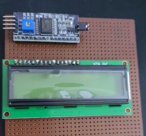
Note that I have used stripboard to solder both I2C and LCD. You can also directly connect I2C with LCD.
Step 2 – Connect the Display setup with Arduino
| Arduino Pin | I2C Pin |
|---|---|
| Analog Pin 4 | SDA |
| Analog Pin 5 | SCL |
| 5v | vcc |
| GND | GND |
Step 3
Once you connect the display with Arduino, upload the I2C Scanner code to get the scanner. Refer the following screenshot for the result of the run.

In the above example the address returned is 0x27. We will be using this in our next sample program to display the text in the 16*2 LCD. Before that install LCD I2C library. Following screenshot will let you know which library to install.

Alternatively you can download your library from https://www.arduinolibraries.info/libraries/keypad and place it in your library folder.
Step 4
Run the following sample program and check the output.
#include <Wire.h>
#include <LCD_I2C.h>
LCD_I2C lcd(0x27, 16, 2);
void setup() {
  // put your setup code here, to run once:
  lcd.begin();
  lcd.backlight();
  lcd.clear();
  lcd.setCursor(2,0);
  lcd.print("Digitalab.org");
}

void loop() {
  // put your main code here, to run repeatedly:


}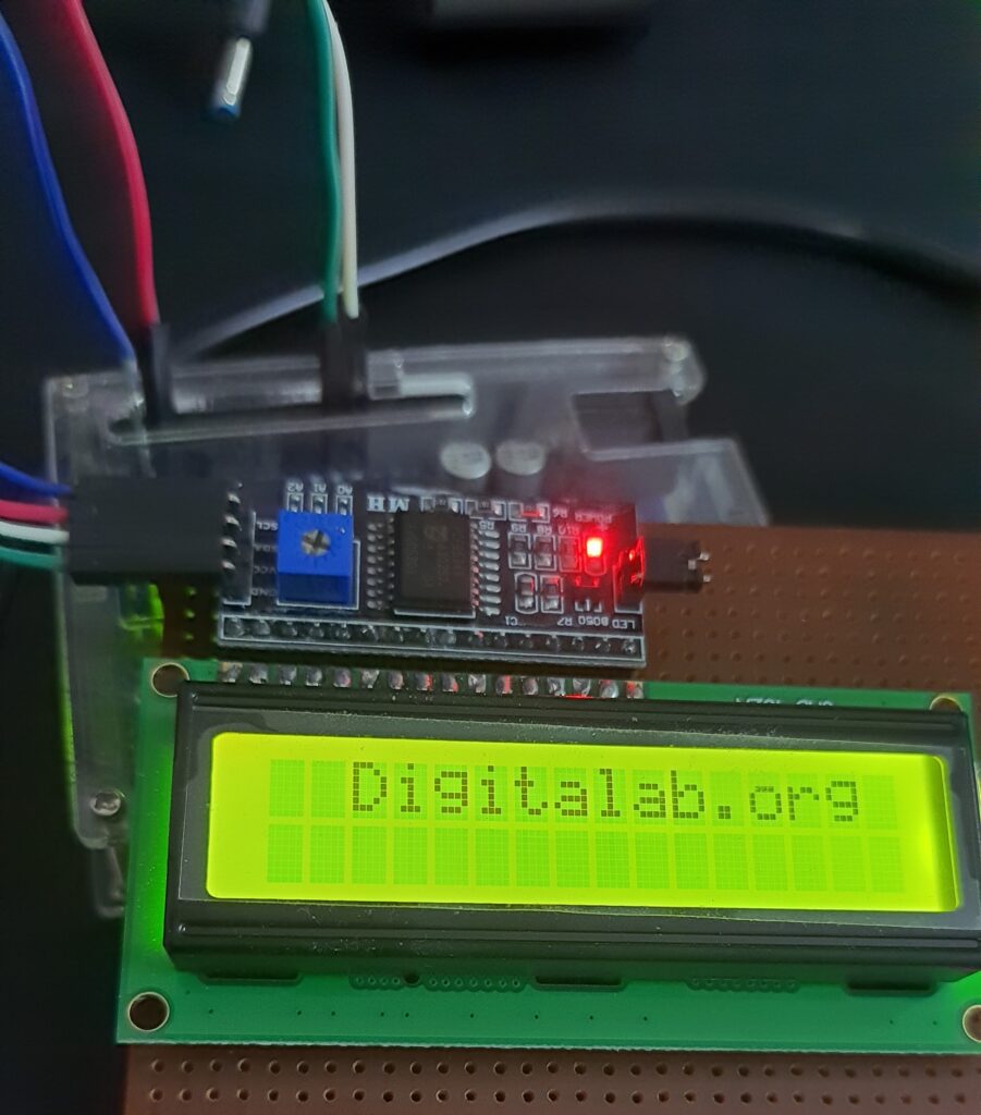
Note : This display setup can be used in all Arduino projects and we only need 4 wires. 2 for data and 2 for power. This16*2 LCD using I2C with Arduino setup will simplify all your Arduino projects display requirement.
Do let me know how it goes for you.