
Introduction
The TEA5767 is a single-chip electronically tuned FM stereo radio module for low-voltage applications with fully integrated Intermediate Frequency (IF) selectivity and- demodulation. The radio is completely adjustment-free and only requires a very few external components. The digital tuning is based on the conventional PLL concept. The power consumption of the tuner is low. The current is about 13mA and the supply voltage can be varied between 2.5 and 5V.
It has a frequency range of between 76 and 108MHz. You can use Arduino to drive this module.
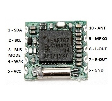
The TEA5767 chip itself is a 40-pin package. The module I have has the chip mounted on a small PCB with most of the required supporting components. It exposes only 10 pins:
| Pin | Name | Description |
| 1 | SDA | I²C data |
| 2 | SCL | I²C clock |
| 3 | BUSMODE | bus mode select input |
| 4 | W/R | write/read control input for the 3-wire bus |
| 5 | VCC | 2.5-5V |
| 6 | GND | ground |
| 7 | ROUT | right audio out |
| 8 | LOUT | left audio out |
| 9 | MPXO | FM demodulator MPX signal output |
| 10 | ANT | antenna in |
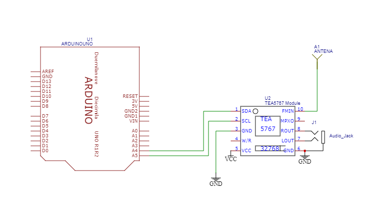
Schematic Diagram
Refer the image below. On the left we have the IC2 connections SDA and SCL that will go to pins A5 and A4 respectively on the Arduino Uno.
The right hand side has a connection ANT (antenna) left and right audio and ground.
Arduino Code
/*

  FM/TEA5767
  Control the TEA5767 low-power FM stereo radio chip with an Arduino.

  For info and circuit diagrams see https://github.com/tardate/LittleArduinoProjects/tree/master/Radio/FM/TEA5767

 */

#include <Wire.h>

// a sampling of India radio stations..
const double STATIONS[] = {
  91.5,
  93.5,
  98.3,
  105.0
};

const double SAMPLE_DELAY = 2000;

void setup() {
  Serial.begin(9600);
  Wire.begin();
  delay(500);
}

void loop() {
  for(int station=0; station < sizeof(STATIONS) / sizeof(double); ++station) {
    setFrequency(STATIONS[station]);
    delay(SAMPLE_DELAY);
  }
}

void setFrequency(double frequency) {
  int frequencyB = 4 * (frequency * 1000000 + 225000) / 32768;
  byte frequencyH = frequencyB >> 8;
  byte frequencyL = frequencyB & 0xFF;

  Serial.print(F("Setting frequency "));
  Serial.println(frequency);
  Wire.beginTransmission(0x60);
  Wire.write(frequencyH & 0b00111111);
  Wire.write(frequencyL);
  Wire.write(0b10110000);
  Wire.write(0b00010000);
  Wire.write(0b00000000);
  Wire.endTransmission();
}
The above code is just sampling. This can be modified to take input from pot or push button.
In my next post will show on how we can modify it to add display and frequency selector.