

In Episode 1, we built a basic ESP32 Wi-Fi scanner and displayed nearby Wi-Fi networks on the Serial Monitor.
In Episode 2, we moved toward a graphical interface by setting up a 2.8-inch TFT display based on the ST7789 controller.
In Episode 3, we bring these two pieces together.
The goal of this episode is to take the Wi-Fi scanning functionality from Episode 1 and display the results directly on the TFT screen.
What We Will Build
By the end of this episode, the ESP32 will:
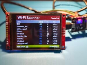
- Scan for nearby Wi-Fi networks
- Display the number of networks detected
- Display SSID
- Display signal strength (RSSI)
- Display Wi-Fi channel
- Display security type
- Refresh the results periodically
- Present the information in a simple dashboard
We will also organize the code into separate files so that the project is easier to maintain and extend in future episodes.
Hardware Used
The hardware remains largely the same as Episode 2.
Main Components
- ESP32 development board – 38-pin
- 2.8-inch 240×320 TFT display
- ST7789 TFT controller
- Jumper wires
- USB cable
The TFT uses the ESP32’s hardware SPI interface.
TFT Pin Configuration
One important change was made during the development of this episode.
The original configuration used GPIO2 for the TFT DC pin:
#define TFT_DC 2
During Wi-Fi scanning, the display would eventually turn completely white.
After systematic troubleshooting, we moved the DC connection to GPIO27.
The final configuration is:
| TFT Pin | ESP32 |
|---|---|
| SCK | GPIO18 |
| MOSI | GPIO23 |
| MISO | GPIO19 |
| CS | GPIO5 |
| DC | GPIO27 |
| RST | GPIO4 |
The important change is:
#define TFT_DC 27instead of:
#define TFT_DC 2This completely resolved the white-screen problem.
TFT Configuration
The project uses TFT_eSPI with the ST7789 driver.The important configuration is:
#define TFT_MOSI 23
#define SPI_READ_FREQUENCY 20000000
#define ST7789_DRIVER
#define TFT_MISO 19
#define TFT_SCLK 18
#define TFT_CS 5
#define TFT_DC 27
#define TFT_RST 4
#define SPI_FREQUENCY 20000000
The display is configured with:
tft.setRotation(3);During Episode 2 we also discovered that the display colors were inverted. This was resolved using:
tft.invertDisplay(false);Starting With the Episode 1 Scanner
The Wi-Fi scanner from Episode 1 already provided most of the functionality we needed.
The original scanner used:
int numberOfNetworks = WiFi.scanNetworks();
WiFi.SSID(i);
WiFi.RSSI(i);
WiFi.channel(i);
WiFi.encryptionType(i);
and then retrieved information such as:
WiFi.BSSIDstr(i);Instead of printing this information to Serial Monitor, Episode 3 sends the information to the TFT display.
Keeping Episode 3 Simple
Initially, there was a temptation to create a much more complex architecture.
However, for this episode we decided to keep the application logic simple.
The display functionality was separated into a DisplayManager, but we didn’t introduce unnecessary layers or complicated design patterns.
This keeps the project understandable while still preparing the code for more advanced features in later episodes.
Project Structure
The project is organized into:
ESP32_WifiScanner
│
├── ESP32_WifiScanner.ino
├── Config.h
├── Theme.h
├── DisplayManager.h
└── DisplayManager.cpp
ESP32_WifiScanner.ino
Contains the main application logic and Wi-Fi scanning.
Config.h
Contains configuration values such as screen dimensions and display layout.
Theme.h
Contains colors used by the user interface.
For example:
#define COLOR_BACKGROUND TFT_BLACK
#define COLOR_HEADER TFT_NAVY
#define COLOR_HEADER_TEXT TFT_WHITE
#define COLOR_COLUMN_BG TFT_DARKGREY
#define COLOR_COLUMN_TEXT TFT_WHITE
#define COLOR_FOOTER TFT_DARKCYAN
#define COLOR_FOOTER_TEXT TFT_WHITE
#define COLOR_TEXT TFT_WHITE
#define COLOR_SIGNAL_STRONG TFT_GREEN
#define COLOR_SIGNAL_MEDIUM TFT_YELLOW
#define COLOR_SIGNAL_WEAK TFT_RED
DisplayManager
Handles the TFT drawing operations, keeping the main application code cleaner.
Source code can be downloaded from Github location : https://github.com/pintushaw/WifiScanner
Designing the Wi-Fi Network List
Each detected network is displayed as a row.
The information includes:
| Column | Information |
|---|---|
| SSID | Wi-Fi network name |
| RSSI | Signal strength |
| CH | Wi-Fi channel |
| Security | Encryption type |
Long SSIDs are shortened so they don’t interfere with the other columns.
Signal Strength Colors
To make the interface easier to understand, RSSI is represented using different colors.
The logic is:
if (rssi > -50)
signalColor = COLOR_SIGNAL_STRONG;
else if (rssi > -70)
signalColor = COLOR_SIGNAL_MEDIUM;
else
signalColor = COLOR_SIGNAL_WEAK;
Therefore:
- Green → Strong signal
- Yellow → Medium signal
- Red → Weak signal
This provides a quick visual indication of network strength.
The Big Problem – White Screen
After integrating the Wi-Fi scanner with the TFT, something unexpected happened. The dashboard appeared correctly when the ESP32 started. The Wi-Fi scan also completed successfully. But after a few seconds:
The entire TFT turned white.
Interestingly, the ESP32 itself continued running. The Serial Monitor continued showing messages such as:
Loop Started
Scan Finished
Networks = 12
Heap = 237568
There was no crash or reset.
Debugging the Problem
Rather than immediately rewriting the application, we investigated the problem step by step.
We added debug statements throughout the application.
For example:
Serial.println("1. Clearing Screen");

Serial.println("2. Starting Scan");

Serial.println("3. Processing Networks");

Serial.println("4. Scan Finished");
This confirmed that the application was continuing to execute normally.
Testing Wi-Fi Scanning
The scanner was returning valid results.
For example:
Networks = 12
Heap = 237568

and later:

Networks = 17
Heap = 237120
The available heap memory remained healthy.
This ruled out an obvious memory exhaustion problem.
Testing With Dummy Data
We then replaced the real Wi-Fi information with fixed test values.
For example:
display.drawNetwork(
i,
"TEST",
\-55,
6,
"WPA2"
);
The display still eventually turned white.
This was an important finding.
It meant the problem wasn’t caused by:
- SSID strings
- RSSI values
- Wi-Fi security strings
- Network information retrieval
Finding the Root Cause
After eliminating the software and rendering issues, we went back to the hardware configuration.
The TFT DC pin was connected to:
GPIO2
The configuration was:
#define TFT_DC 2GPIO2 is one of the ESP32’s special boot/strapping pins.
Although it worked reliably during the simpler TFT application in Episode 2, the combination of continuous Wi-Fi activity and TFT communication in Episode 3 resulted in unreliable display behavior.
The Fix
We moved the TFT DC connection from:
GPIO2
to:
GPIO27
and changed the configuration to:
#define TFT_DC 27After uploading the code again, the problem disappeared.
The ESP32 could now continuously scan Wi-Fi networks while updating the TFT without the display turning white.
Final Result
We now have a working portable Wi-Fi scanner with a graphical interface.
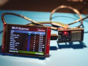
The ESP32:
- Initializes the TFT.
- Displays the dashboard.
- Starts a Wi-Fi scan.
- Detects nearby networks.
- Displays the results.
- Shows RSSI using colors.
- Displays channel and security information.
- Repeats the process.
The final result is much more useful than the Serial Monitor-based scanner from Episode 1.
Final Pin Configuration
The final TFT configuration is:
#define TFT_MISO 19

#define TFT_MOSI 23

#define TFT_SCLK 18

#define TFT_CS 5

#define TFT_DC 27

#define TFT_RST 4

And the display configuration is:

#define ST7789_DRIVER

#define SPI_FREQUENCY 20000000

#define SPI_READ_FREQUENCY 20000000
YouTube video
For a step by step guide watch my youtube video below.