

In the previous episode, we expanded our ESP32 WiFi Scanner by adding BLE scanning and battery/power support. In this episode, we take the project one step further by introducing a touchscreen-based navigation system.
The goal of EP5 is to transform the scanner from a simple display-based application into a more complete touch-controlled handheld network scanner.
This episode is divided logically into two parts:
- Part 1 – Touch Framework Setup — testing, calibration and navigation
- Part 2 – Navigation Integration — connecting the framework with the WiFi/BLE functionality from EP4 and refining the UI
What We Are Building
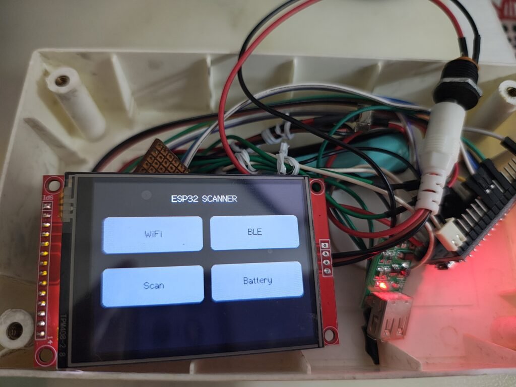
The final interface contains a Home screen with four options:
- WiFi
- BLE
- Scan
- Battery
The WiFi and BLE screens connect to the scanner functionality developed in previous episodes, while the Battery screen provides the initial user interface for battery information.
The final navigation looks like this:
                       HOME
                        │
          ┌─────────────┼─────────────┐
          │             │             │
          ▼             ▼             ▼
        Wi-Fi           BLE        Battery
          │             │             │
       Scan           Scan        UI/Dummy
          │             │             │
       10 sec         10 sec          │
       refresh        refresh         │
          │             │             │
          └─────────────┼─────────────┘
                        │
                       HOME
Part 1 – Touchscreen Framework Setup
The first objective was to build the touchscreen functionality independently of the existing WiFi and BLE scanner.
This makes the development easier because we can verify the touchscreen hardware and navigation before introducing additional application logic.
Touchscreen
The project uses a 2.8-inch SPI TFT display with an XPT2046 touch controller.
The touch controller communicates with the ESP32 through SPI.
The touch connections used in this project are:
| TFT Touch Screen | ESP32 |
|---|---|
| T_DO | GPIO16 |
| T_DIN | GPIO17 |
| T_CLK | GPIO32 |
| T_CS | GPIO25 |
| T_IRQ | GPIO26 |
The existing TFT display continues to use its own SPI configuration.
Touch Library
The project uses:
#include <XPT2046_Touchscreen.h>The touch interface is initialized using a separate SPI interface:
SPIClass touchSPI(HSPI);

touchSPI.begin(
TOUCH_CLK,
TOUCH_MISO,
TOUCH_MOSI,
-1
);

XPT2046_Touchscreen touch(
TOUCH_CS,
TOUCH_IRQ
);

touch.begin(touchSPI);
This allows the touchscreen to communicate independently while the TFT continues to operate normally.
Testing Touch Input
Before implementing navigation, we will first verify that the touchscreen was actually responding.
The raw X and Y coordinates were printed to the Serial Monitor whenever the display was touched. Use the below code from GitHub to test the touch input. This will also confirm the wiring and if any issues it will show up at this moment.
ESP32_WifiScanner_Calibrationtest
Touching different areas of the screen produced different raw coordinate values. This is an important step because the raw coordinates from the XPT2046 do not necessarily correspond directly to the TFT’s screen coordinates.
Touchscreen Calibration
The next step was calibration.
The TFT display is configured as a 320 x 240 display. The raw X/Y values from the XPT2046 therefore need to be mapped to the actual display coordinates.
After calibration, we will be able to accurately detect touches in different areas of the display. Use the below code to calibrate your display.
ESP32_WifiScanner_touchcalibrationV2
Creating the Navigation Framework
Once touch detection is working, next step is to we introduce the concept of screen states.
The project now has four primary screens:
SCREEN_HOME
SCREEN_WIFI
SCREEN_BLE
SCREEN_BATTERY
The current screen determines how touch input is interpreted.
In this step we first create Home Screen which contains 4 buttons. Wifi, BLE, Scan, Battery
┌─────────────┐  ┌─────────────┐
│    WiFi     │  │     BLE     │
└─────────────┘  └─────────────┘

┌─────────────┐  ┌─────────────┐
│    Scan     │  │   Battery   │
└─────────────┘  └─────────────┘
In this version/episode only Wifi and BLE button works. The Scan button is currently a placeholder and can be used for a future feature. The Battery button leads to the dummy Battery screen, which will be developed further in a future episode.
Testing Navigation
At this stage, the scanner functionality was not yet connected.
The purpose was simply to verify:
Home → WiFi
Home → BLE
Home → Battery
WiFi → Home
BLE → Home
Battery → Home
Once this navigation was working reliably, we moved to the second part of EP5.
Below file will help test the Button layout in Home screen and Navigation.
ESP32_WifiScanner_ButtonFrameworkv1
ESP32_WifiScanner_touch_navigationTest
So far we covered Wiring, Testing touch data transfer, and Home Screen button layout with navigation. This covers our Part 1 of the project.
Part 2 – Integrating the EP4 Code
With the touchscreen framework working, the next step is to integrate it with the existing WiFi and BLE scanner functionality. This is where the project starts becoming a complete handheld interface.
Integrating the WiFi Scanner
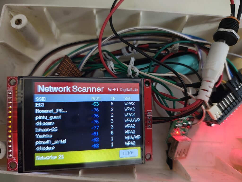
Selecting the WiFi button now changes the current screen to:
SCREEN_WIFIand starts the existing WiFi scanning functionality.
The existing WiFi information will be displayed:
- SSID
- RSSI
- Channel
- Security
The existing signal-strength visualization is also retained.
DisplayManager Improvements
Another important part of EP5 was improving the organization of the display code.
The project uses a dedicated:
DisplayManagerto handle the TFT user interface.
It now contains functionality for:
- Home screen
- Headers
- Column headers
- Footers
- WiFi network display
- BLE device display
- Navigation buttons
- Battery screen
- Messages
This keeps display-specific code out of the main application logic.
The main sketch can therefore concentrate on:
- Touch
- Navigation
- WiFi scanning
- BLE scanning
- Timing
Battery Screen
A Battery screen is also added in this project. The actual battery measurement hardware is not yet connected, so the current screen uses dummy values.
The final battery monitoring hardware will be implemented in a future episode using the 18650 Li-ion battery and the ESP32 ADC.
Final Result
After completing the integration, the ESP32 WiFi Scanner has evolved into a multi-screen touch-controlled application.
The final interface provides:
Home
Navigation to all available functions.
WiFi
- WiFi scanning
- SSID
- RSSI
- Channel
- Security
- Automatic 10-second refresh
BLE
- BLE scanning
- Device name
- RSSI
- Automatic refresh
Battery
- Battery percentage UI
- Battery voltage UI
- Graphical battery indicator
- Real measurement planned for a future episode
Project Architecture After EP5
The overall architecture is now:
                  ESP32
                    │
          ┌─────────┴─────────┐
          │                   │
       Touch               Scanner
          │                   │
      XPT2046             WiFi / BLE
          │                   │
          └─────────┬─────────┘
                    │
              Navigation
                    │
                    ▼
             DisplayManager
                    │
       ┌────────────┼────────────┐
       │            │            │
      Home         WiFi         BLE
                                  │
                              Battery
This architecture gives us a good foundation for adding more features without having to redesign the user interface.
Youtube Video of the Project
Conclusion
This version is an important step in the ESP32 WiFi Scanner project. We started with a working WiFi/BLE scanner and transformed it into a touch-controlled multi-screen interface. The project now has a solid foundation for future functionality while keeping the display and application logic cleanly separated.
Let me know if you are able to build the project and how it goes for you. Any enhancement and feedback, update it in comment.