

In Episode 6 of the ESP32 Portable WiFi Scanner project, we take the project one step further by adding battery monitoring.
The scanner is designed to run as a portable device using an 18650 Li-ion battery, so being able to see the battery voltage and approximate battery percentage directly on the TFT display makes the project much more practical.
In this episode, we connect the battery to an ESP32 ADC input through a 100kΩ + 100kΩ voltage divider, read the battery voltage using analogReadMilliVolts(), calculate the battery percentage, and display the result on the touchscreen.
What We Added in EP6
The main additions in this episode are:
- 18650 Li-ion battery monitoring
- Battery voltage measurement
- ESP32 ADC using GPIO34
- 100kΩ + 100kΩ voltage divider
- Battery percentage calculation
- Battery status screen on the TFT
- Battery disconnected detection
- Automatic battery-status refresh
- Integration with the existing touchscreen navigation
The existing WiFi scanner, BLE scanner, TFT display and touch interface remain part of the project.
ESP32 WiFi Scanner Hardware
The portable scanner currently consists of:
- ESP32 development board
- 2.8-inch TFT touchscreen
- XPT2046 touch controller
- 18650 Li-ion battery
- 5V boost converter
- Battery voltage divider ( 100K resistance -2)
The battery provides the portable power source, while the boost converter provides the required 5V supply for the ESP32/display setup. The battery monitoring circuit itself is independent of the 5V boost output.
Measuring the 18650 Battery Voltage
An ESP32 ADC input cannot be connected directly to a fully charged 18650 battery because a Li-ion cell can reach approximately 4.2V.
Instead, we use a simple voltage divider.
Voltage Divider
The circuit used in this project is:
Battery +
    |
   100kΩ
    |
    +------ GPIO34 (ESP32 ADC)
    |
   100kΩ
    |
   GND
With two equal resistors, the voltage at GPIO34 is approximately half the battery voltage.
For example:
Battery = 4.20V

GPIO34 ≈ 4.20 / 2
       ≈ 2.10V
This keeps the voltage presented to the ADC within a safer range.
Why GPIO34?
GPIO34 was selected as the battery ADC input.
One advantage of GPIO34 is that it is an ADC input-only GPIO, making it suitable for measuring an external analog voltage.
The battery voltage is therefore measured without using any of the GPIOs already occupied by the TFT, touch controller or other project hardware.
Reading the ADC Voltage
The ESP32 provides analogReadMilliVolts() for reading the ADC voltage.
The basic function used in the project is:
float readBatteryVoltage()
{
    uint32_t adcVoltage = analogReadMilliVolts(BATTERY_ADC_PIN);

    float batteryVoltage = (adcVoltage * BATTERY_DIVIDER_RATIO) / 1000.0;

    return batteryVoltage;
}
The important point here is that analogReadMilliVolts() gives us the voltage measured at the ADC pin. Because our voltage divider reduces the battery voltage by half, we multiply the result by the divider ratio.
For our 100kΩ + 100kΩ divider:
#define BATTERY_DIVIDER_RATIO 2.0
For example, if the ADC measures:
1.935V
the estimated battery voltage becomes:
1.935 × 2 = 3.87V
The TFT display can then show:
3.87 VConfiguring the ESP32 ADC
The ADC attenuation is configured during setup:
analogSetPinAttenuation(
    BATTERY_ADC_PIN,
    ADC_11db
);
This provides an appropriate measurement range for the voltage coming from the divider.
The important thing is to make sure the actual voltage reaching GPIO34 remains within the ESP32’s permitted input range.
Calculating Battery Percentage
Voltage is useful, but a percentage is easier to understand while using a portable device.
For this project, we use a simple linear approximation:
4.20V → 100%
3.00V → 0%
The calculation is:
int calculateBatteryPercentage(float voltage)
{
    int percentage =
        (int)(((voltage - 3.00) /
        (4.20 - 3.00)) * 100.0);

    return constrain(
        percentage,
        0,
        100
    );
}
For example:
| Battery Voltage | Approx. Display |
|---|---|
| 4.20V | 100% |
| 4.00V | 83% |
| 3.87V | 72% |
| 3.70V | 58% |
| 3.50V | 42% |
| 3.30V | 25% |
| 3.00V | 0% |
Important Note
This is a simple voltage-based estimate, not a true fuel-gauge measurement.
The actual percentage of a Li-ion battery depends on load, battery chemistry, discharge characteristics and whether the battery is resting or powering the device. For this project, the voltage-based approach is sufficient to provide a useful battery status indication.
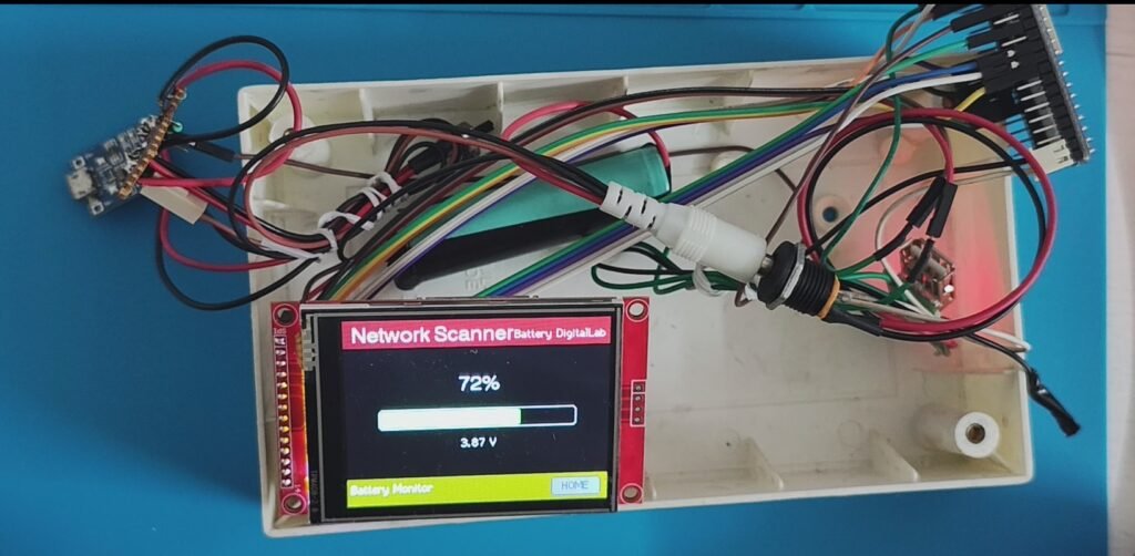
Battery Monitor Screen
A dedicated Battery screen is added to the TFT interface.
The screen displays:
- Battery percentage
- Graphical battery bar
- Battery voltage
- Battery Monitor footer
- HOME button
For example:
        72%

   ┌───────────────┐
   │██████████     │
   └───────────────┘

        3.87 V

Battery Monitor             HOME
The battery bar also changes according to the approximate battery level.
Battery Status Automatically Refreshes
The battery value should not remain fixed after opening the Battery screen. Therefore, EP6 adds automatic battery updates.The scanner periodically reads the battery voltage and updates the TFT.
The update interval used in the project is:
const unsigned long BATTERY_UPDATE_INTERVAL = 10000;
This means the battery information is refreshed approximately every 10 seconds while the Battery screen is active.
Handling a Disconnected Battery
During development, there is an important problem. When the ESP32 is connected to the computer through USB for programming, the 18650 battery may be disconnected. In that situation, GPIO34 is not connected to a valid battery voltage.
An ADC input that is effectively floating can produce unpredictable readings.
For example, the software may report values such as:
6.25 V
0.28 V
5.94 V
3.17 V
4.04 V
even though there is no battery connected. Simply checking whether the measured voltage is greater than zero is therefore not sufficient.
Detecting Battery Disconnection
Instead of adding another hardware circuit, EP6 handles this situation in software. We take three ADC readings with a small delay between them:
bool isBatteryConnected()
{
    float v1 = readBatteryVoltage();
    delay(20);

    float v2 = readBatteryVoltage();
    delay(20);

    float v3 = readBatteryVoltage();

    float minVoltage =
        min(v1, min(v2, v3));

    float maxVoltage =
        max(v1, max(v2, v3));

    Serial.print("Battery Test: ");
    Serial.print(v1, 2);
    Serial.print(" V, ");
    Serial.print(v2, 2);
    Serial.print(" V, ");
    Serial.print(v3, 2);
    Serial.println(" V");

    if (minVoltage < 3.0 ||
        maxVoltage > 4.3)
    {
        return false;
    }

    if ((maxVoltage - minVoltage) > 0.2)
    {
        return false;
    }

    return true;
}
The logic checks two things:
1. Valid Li-ion voltage range
The readings should remain approximately between:
3.0V and 4.3V2. Reading stability
The three readings should not differ by more than:
0.2VThis helps distinguish a real battery voltage from a floating ADC input producing unstable values.
Battery Disconnected Screen
When the battery is not detected, the scanner no longer displays a misleading battery percentage.
Instead, it shows: Battery disconnected along with a message asking the user to connect the battery.
This is particularly useful while programming and testing the device over USB.
One Important Debugging Lesson
During development, adding the battery ADC initialization appeared to cause the TFT screen to turn black.
The problem initially looked like an ADC or GPIO conflict. After debugging the startup sequence, the actual problem was found: the display and touch initialization were being performed twice.
The important lesson was to ensure that:
display.begin();
touch.begin();
are each called only once during setup. After removing the duplicate initialization, the TFT returned to normal operation.
This was a useful reminder that when adding a new hardware feature causes an unrelated component to fail, the problem is not necessarily with the newly added hardware.
Final EP6 Architecture
At this stage, the ESP32 Portable WiFi Scanner supports four main screens:
              HOME
                |
     ┌──────────┼──────────┐
     ↓          ↓          ↓
   WiFi        BLE      Battery
   Scan        Scan      Monitor
Complete Code
Complete code for the project can be found at below GitHub location.
https://github.com/pintushaw/WifiScanner/tree/main/ESP32_WifiScanner_EP6
What’s Next?
With battery monitoring working, the ESP32 WiFi Scanner is becoming much closer to a practical portable device.
The project now combines:
- WiFi scanning
- BLE scanning
- Touchscreen navigation
- Network information display
- Battery voltage monitoring
- Battery percentage
- Battery disconnect detection
- Automatic screen updates
- Portable battery power
There are still several areas that can be improved, including more accurate battery percentage estimation, power consumption monitoring, battery charging status and enclosure design.
Below is the Youtube video of the complete episode 6 project.