

Introduction
Welcome to Episode 2 of the ESP32 Wi-Fi Scanner Project.
In Episode 1, we built a basic Wi-Fi scanner that displayed nearby Wi-Fi networks on the Serial Monitor.
In this episode, we’ll take the project to the next level by replacing the Serial Monitor with a 2.8-inch SPI TFT display. By the end of this tutorial, you’ll have a fully functional display framework that will serve as the foundation for the upcoming episodes.
During this project, I also encountered an interesting compatibility issue—the display was sold as an ILI9341 module but only worked correctly after configuring it as an ST7789 display. I’ll walk you through the complete troubleshooting process so you can avoid spending hours debugging the same problem.
Project Overview
In this episode we will:
- Interface a 2.8-inch SPI TFT display with ESP32
- Configure the TFT_eSPI library
- Draw text and graphics
- Build the display framework for future episodes
- Troubleshoot common TFT display problems
- Prepare the project for the Wi-Fi Scanner user interface
Hardware Required
| Component | Quantity |
|---|---|
| ESP32 DevKit V1 (38 Pin) | 1 |
| 2.8-inch SPI TFT Display | 1 |
| Breadboard | 1 (optional – If using male connecting wire) |
| Jumper Wires | As Required |
| USB Cable | 1 |
TFT Display Specifications
The display used in this project features:
- 2.8-inch Color TFT LCD
- Resolution: 240 × 320 pixels
- SPI Interface
- Integrated Touch Controller
- MicroSD Card Slot
- 65K Colors
Although the product listing described the display as an ILI9341, the working configuration turned out to be different. Sourced from Robu.in
Wiring Diagram
| TFT Pin | ESP32 Pin |
|---|---|
| VCC | 5V |
| GND | GND |
| CS | GPIO 5 |
| RESET | GPIO 4 |
| DC | GPIO 2 |
| SDI (MOSI) | GPIO 23 |
| SCK | GPIO 18 |
| SDO (MISO) | GPIO 19 |
| LED | 3.3V |
Note: The touch controller pins are not used in this episode.
Installing TFT_eSPI Library
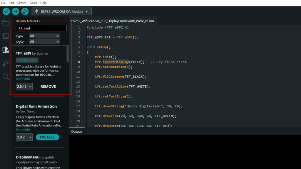
- Open Arduino IDE and Go to “Tools” ->”Manage Libraries…”
- Search for “TFT_eSPI”
- Install the latest version of the Libraries by “Bodmer“
TFT_eSPI Configuration
After installation of the libraries Locate the library folder:
Documents -> Arduino -> libraries -> TFT_eSPI
Open:
User_Setup_Select.h
Comment out all existing #include lines and enable only one:
#include <User_Setup.h>After this open, User_Setup.h and replace the content with the following code.
#ifndef USER_SETUP_H
#define USER_SETUP_H

// Display Driver
#define ILI9341_DRIVER

// ESP32 SPI Pins
#define TFT_MISO 19
#define TFT_MOSI 23
#define TFT_SCLK 18

// Control Pins
#define TFT_CS   5
#define TFT_DC   2
#define TFT_RST  4

// SPI Frequency
#define SPI_FREQUENCY  40000000
#define SPI_READ_FREQUENCY 20000000

// Fonts
#define LOAD_GLCD
#define LOAD_FONT2
#define LOAD_FONT4
#define LOAD_FONT6
#define LOAD_FONT7
#define LOAD_FONT8
#define LOAD_GFXFF

#define SMOOTH_FONT

#endif
Note: Initially the display was configured using:
#define ILI9341_DRIVERThe result was:
- Blank strip on the display
- Shifted graphics
- Incorrect screen orientation
- Inverted colors
After several tests, the display finally worked correctly using:
#define ST7789_DRIVERDisplay Initialization and Drawing Graphics
Use the below code for testing the display.
#include <TFT_eSPI.h>

TFT_eSPI tft = TFT_eSPI();

void setup()
{
    tft.init();

    tft.setRotation(1);

    tft.fillScreen(TFT_BLACK);

    tft.setTextColor(TFT_WHITE);

    tft.setTextSize(2);

    tft.drawString("Hello DigitalLab!", 30, 20);

    tft.drawLine(20, 60, 300, 60, TFT_GREEN);

    tft.drawRect(20, 80, 120, 60, TFT_RED);

    tft.fillCircle(220, 110, 30, TFT_BLUE);

    tft.fillRoundRect(20, 170, 120, 40, 8, TFT_YELLOW);

    tft.setTextColor(TFT_BLACK);

    tft.drawCentreString("OK", 80, 182, 2);
}

void loop()
{
}
Compile the code and upload it to ESP32 using Arduino IDE.
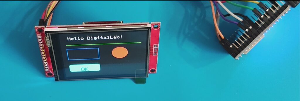
You can also download the code from following Github location:
https://github.com/pintushaw/WifiScanner
Troubleshooting
Problem 1 – White Screen
Symptom
The display remained blank after power-up.
Solution
Power the TFT display using 5V instead of 3.3V.
Problem 2 – Blank Strip on the Screen
Symptom
The display showed a blank vertical strip and graphics appeared shifted.
Cause
The display was configured as an ILI9341 controller.
Solution
Use the ST7789 driver instead.
#define ST7789_DRIVERProblem 3 – Upside Down Display
Solution
tft.setRotation(3);Problem 4 – Incorrect Colors
The background appeared white while text appeared black.
The fix was simply:
tft.invertDisplay(false);Lessons Learned
One interesting finding from this project was that not every display module matches the controller advertised by the seller. Although this display was listed as an ILI9341, it behaved like an ST7789-compatible module.
This experience highlights the importance of testing different driver configurations before assuming the hardware is faulty.
Source Code
The complete Arduino sketch used in this tutorial is available on GitHub.
https://github.com/pintushaw/WifiScanner
What’s Next?
Now that the display is fully functional, the next episode will focus on building the actual Wi-Fi scanner dashboard.
We’ll add:
- Wi-Fi network scanning
- SSID list
- RSSI values
- Signal strength indicators
- Security type
- Professional user interface
Stay tuned for Episode 3!
Youtube video
Conclusion
In this episode, we successfully interfaced a 2.8-inch SPI TFT display with the ESP32 and built the foundation for our portable Wi-Fi scanner. Along the way, we solved several real-world compatibility issues involving display drivers, screen orientation, and color inversion.
With the display framework complete, we’re now ready to build a polished graphical interface for the Wi-Fi scanner in the next episode.